EVPN – All-active multihoming

So this is the fourth blog on EVPN, the previous blogs covered the following topics:

  • EVPN basics, route-types and basic L2 forwarding
  • EVPN IRB and Inter-VLAN routing
  • EVPN single-active multi-homing

This post will cover the ability of EVPN to provide all-active multi-homing for layer-2 traffic, where the topology contains two different active PE routers, connecting to a switch via a LAG, the setup is similar to the previous labs. Due to some restrictions and in the interests of simplicity, this lab will cover all-active multi-homing for a single VLAN only, (VLAN 100 in this case) consider the network topology:

Capture5

The topology and general connectivity is the same as the other previous examples, the two big differences are that only VLAN 100 is present here and the connectivity between MX-1 and MX-2 is now using MC-LAG.

The first consideration that needs to be made when running EVPN in all-active mode, is that it must connect to the upstream devices using some sort of LAG, or MC-LAG – consider the wording from the RFC 7432:


https://tools.ietf.org/html/rfc7432#section-14.1.2

“If a bridged network is multihomed to more than one PE in an EVPN network via switches, then the support of All-Active redundancy mode requires the bridged network to be connected to two or more PEs using a LAG.”

Essentially, this boils down to some basic facts around how switches work – you can’t have two different PE routers with active access-interfaces configured with the same mac-address, spanning two different control-planes, for the simple reason that you’ll create a duplicate mac-address in the layer-2 network, which will cause a nightmare.

Consider the below scenario:

Capture6

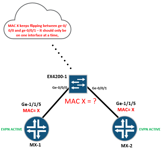
I tried this in a lab before I read the RFC, and discovered that EX4200-1 floods egress traffic to MX-1 and MX-2, resulting in lots of traffic duplication and flooding, simply because each time a packet lands on ge-0/0/0 or ge-0/0/1 from MX-1 or MX-2 with mac-address “X” the switch has to update it’s CAM table, so essentially the whole thing is broken – which explains the wording of the RFC in relation to all-active mode.

With Juniper the way to get around this problem is simply to convert the Ethernet interfaces connecting to EX4200-1 to a basic MC-LAG configuration, we don’t need to configure ICCP or any serious multi-chassis configuration – we just need to make sure the LACP system-id is identical on MX-1 and MX-2, so that the EX4200 think’s it’s connected to a single downstream device,

Lets check the LAG configuration on MX-1 and MX-2;

MX-1

  1. tim@MX5-1> show configuration interfaces ae0
  2. description “MCLAG to EX4500-1”;
  3. flexible-vlan-tagging;
  4. encapsulation flexible-ethernet-services;
  5. esi {
  6.     00:11:22:33:44:55:66:77:88:99;
  7.     all-active;
  8. }
  9. aggregated-ether-options {
  10.     lacp {
  11.         system-id 00:00:00:00:00:01;
  12.     }
  13. }
  14. unit 100 {
  15.     encapsulation vlan-bridge;
  16.     vlan-id 100;
  17.     family bridge;
  18. }


MX-2

  1. tim@MX5-2> show configuration interfaces ae0
  2. description “MCLAG to EX4500-1”;
  3. flexible-vlan-tagging;
  4. encapsulation flexible-ethernet-services;
  5. esi {
  6.     00:11:22:33:44:55:66:77:88:99;
  7.     all-active;
  8. }
  9. aggregated-ether-options {
  10.     lacp {
  11.         system-id 00:00:00:00:00:01;
  12.     }
  13. }
  14. unit 100 {
  15.     encapsulation vlan-bridge;
  16.     vlan-id 100;
  17.     family bridge;
  18. }


And finally on EX4200-1 we have a basic standard LAG configuration, with nothing fancy or sexy going on 🙂

EX4200-1


  1. imtech@ex4200-1> show configuration interfaces ae0
  2. aggregated-ether-options {
  3.     lacp {
  4.         active;
  5.     }
  6. }
  7. unit 0 {
  8.     family ethernet-switching {
  9.         port-mode trunk;
  10.         vlan {
  11.             members vlan-100;
  12.         }
  13.     }
  14. }
  15. {master:0}
  16. imtech@ex4200-1>


From the perspective of the EX4200, it’s just a totally standard LAG with two interfaces running LACP, so long as we have EVPN all-active configured correctly on MX-1 and MX-2 everything is taken care of.

EX4200-1 verification:

  1. imtech@ex4200-1> show lacp interfaces
  2. Aggregated interface: ae0
  3.     LACP state:       Role   Exp   Def  Dist  Col  Syn  Aggr  Timeout  Activity
  4.       ge-0/0/0       Actor    No    No   Yes  Yes  Yes   Yes     Fast    Active
  5.       ge-0/0/0     Partner    No    No   Yes  Yes  Yes   Yes     Fast   Passive
  6.       ge-0/0/1       Actor    No    No   Yes  Yes  Yes   Yes     Fast    Active
  7.       ge-0/0/1     Partner    No    No   Yes  Yes  Yes   Yes     Fast   Passive
  8.     LACP protocol:        Receive State  Transmit State          Mux State
  9.       ge-0/0/0                  Current   Fast periodic Collecting distributing
  10.       ge-0/0/1                  Current   Fast periodic Collecting distributing
  11. {master:0}
  12. imtech@ex4200-1>


Aside from the fact we’ve converted the access Ethernet interfaces to MC-LAG on MX-1 and MX-2, lets check to see what’s changed with the EVPN configuration in order to get all-active EVPN working, first lets check MX-1:

  1. tim@MX5-1> show configuration routing-instances
  2. EVPN-100 {
  3.     instance-type virtual-switch;
  4.     route-distinguisher 1.1.1.1:100;
  5.     vrf-target target:100:100;
  6.     protocols {
  7.         evpn {
  8.             extended-vlan-list 100;
  9.             default-gateway do-not-advertise;
  10.         }
  11.     }
  12.     bridge-domains {
  13.         VL-100 {
  14.             vlan-id 100;
  15.             interface ae0.100;
  16.             routing-interface irb.100;
  17.         }
  18.     }
  19. }
  20. VPN-100 {
  21.     instance-type vrf;
  22.     interface irb.100;
  23.     route-distinguisher 100.100.100.1:100;
  24.     vrf-target target:1:100;
  25.     vrf-table-label;
  26. }
  27. tim@MX5-1>


The configuration is absolutely identical on MX-2, you’ll notice that the only thing which has changed on MX-1, is that the physical interface of ge-1/1/5 has changed to the new LAG interface of ae0.100 for VLAN 100, everything else is exactly the same as the previous single-active example from last week, lets take a closer look at the interface on MX-1

  1. tim@MX5-1> show configuration interfaces ae0
  2. description “MCLAG to EX4500-1”;
  3. flexible-vlan-tagging;
  4. encapsulation flexible-ethernet-services;
  5. esi {
  6.     00:11:22:33:44:55:66:77:88:99;
  7.     all-active;
  8. }
  9. aggregated-ether-options {
  10.     lacp {
  11.         system-id 00:00:00:00:00:01;
  12.     }
  13. }
  14. unit 100 {
  15.     encapsulation vlan-bridge;
  16.     vlan-id 100;
  17.     family bridge;
  18. }


It’s clear to see that under the interface ESI configuration, we’re changed the ESI mode from single-active, to “all-active” which again should be self explanatory to most readers 🙂 and again note, that this configuration is 100% identical on both Mx-1 and MX-2,

Lets check the EVPN instance and see what’s changed since the single-active example:

  1. tim@MX5-1> show evpn instance extensive
  2. Instance: EVPN-100
  3.   Route Distinguisher: 1.1.1.1:100
  4.   Per-instance MAC route label: 299776
  5.   MAC database status                Local  Remote
  6.     Total MAC addresses:                13      96
  7.     Default gateway MAC addresses:       1       0
  8.   Number of local interfaces: 1 (1 up)
  9.     Interface name  ESI                            Mode             Status
  10. ae0.100         00:11:22:33:44:55:66:77:88:99  all-active       Up
  11.   Number of IRB interfaces: 1 (1 up)
  12.     Interface name  VLAN ID  Status  L3 context
  13.     irb.100         100      Up      VPN-100
  14.   Number of bridge domains: 1
  15.     VLAN ID  Intfs / up    Mode             MAC sync  IM route label
  16.     100          1   1     Extended         Enabled   300432
  17.   Number of neighbors: 2
  18.     10.10.10.2
  19.       Received routes
  20.         MAC address advertisement:             49
  21.         MAC+IP address advertisement:           0
  22.         Inclusive multicast:                    1
  23.         Ethernet auto-discovery:                2
  24.     10.10.10.3
  25.       Received routes
  26.         MAC address advertisement:             60
  27.         MAC+IP address advertisement:           0
  28.         Inclusive multicast:                    1
  29.         Ethernet auto-discovery:                0
  30.   Number of ethernet segments: 1
  31.     ESI: 00:11:22:33:44:55:66:77:88:99
  32.       Status: Resolved by IFL ae0.100
  33. Local interface: ae0.100, Status: Up/Forwarding
  34.       Number of remote PEs connected: 1
  35.         Remote PE        MAC label  Aliasing label  Mode
  36.         10.10.10.2       300416     300416          all-active  
  37.       Designated forwarder: 10.10.10.1
  38.       Backup forwarder: 10.10.10.2
  39.       Advertised MAC label: 300400
  40.       Advertised aliasing label: 300400
  41.       Advertised split horizon label: 300416
  42. Instance: __default_evpn__
  43.   Route Distinguisher: 10.10.10.1:0
  44.   Number of bridge domains: 0
  45.   Number of neighbors: 1
  46.     10.10.10.2
  47.       Received routes
  48.         Ethernet Segment:                       1
  49. tim@MX5-1>


So we can see that MX-1 has changed from single-active to all-active, and is in the up/forwarding state,

Lets check MX-2 to see what it looks like:

  1. tim@MX5-2> show evpn instance extensive
  2. Instance: EVPN-100
  3.   Route Distinguisher: 1.1.1.2:100
  4.   Per-instance MAC route label: 299776
  5.   MAC database status                Local  Remote
  6.     Total MAC addresses:                47      64
  7.     Default gateway MAC addresses:       1       0
  8.   Number of local interfaces: 1 (1 up)
  9.     Interface name  ESI                            Mode             Status
  10. ae0.100         00:11:22:33:44:55:66:77:88:99  all-active       Up
  11.   Number of IRB interfaces: 1 (1 up)
  12.     Interface name  VLAN ID  Status  L3 context
  13.     irb.100         100      Up      VPN-100
  14.   Number of bridge domains: 1
  15.     VLAN ID  Intfs / up    Mode             MAC sync  IM route label
  16.     100          1   1     Extended         Enabled   300528
  17.   Number of neighbors: 2
  18.     10.10.10.1
  19.       Received routes
  20.         MAC address advertisement:             14
  21.         MAC+IP address advertisement:           1
  22.         Inclusive multicast:                    1
  23.         Ethernet auto-discovery:                2
  24.     10.10.10.3
  25.       Received routes
  26.         MAC address advertisement:             60
  27.         MAC+IP address advertisement:           0
  28.         Inclusive multicast:                    1
  29.         Ethernet auto-discovery:                0
  30.   Number of ethernet segments: 1
  31.     ESI: 00:11:22:33:44:55:66:77:88:99
  32.       Status: Resolved by IFL ae0.100
  33. Local interface: ae0.100, Status: Up/Forwarding
  34.       Number of remote PEs connected: 1
  35.         Remote PE        MAC label  Aliasing label  Mode
  36. 10.10.10.1       300400     300400          all-active
  37. Designated forwarder: 10.10.10.1
  38.       Backup forwarder: 10.10.10.2
  39.       Advertised MAC label: 300416
  40.       Advertised aliasing label: 300416
  41.       Advertised split horizon label: 300432
  42. Instance: __default_evpn__
  43.   Route Distinguisher: 10.10.10.2:0
  44.   Number of bridge domains: 0
  45.   Number of neighbors: 1
  46.     10.10.10.1
  47.       Received routes
  48.         Ethernet Segment:                       1
  49. tim@MX5-2>


Excellent! both MX-1 and MX-2 are in the up/forwarding state for VLAN 100, meaning that in theory – they can both send and receive traffic received on their access LAG interface, and the MPLS side – you’ll also notice how simple it is to get working.

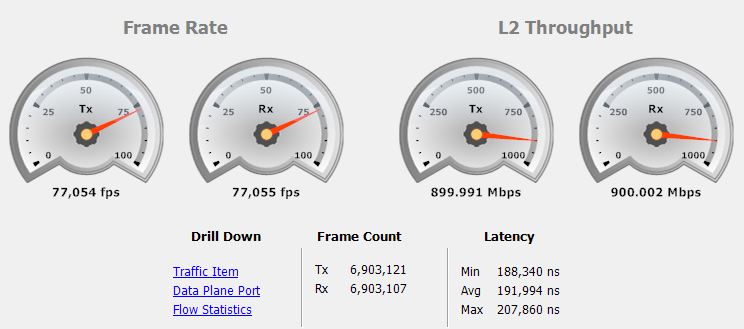
I currently have 50x IXIA hosts sat behind MX-1 and MX-2, and a further 50x hosts sat behind MX-3, 50Mbps of traffic is being sent bi-bidirectionally between each IXIA host, lets recap the diagram:

Capture7

With an active-active configuration, traffic from multiple hosts at the top of the network, should be sent towards MX-1 and MX-2 by EX4200-1 according to it’s standard LAG hashing algorithm, (source/destination mac) because I have 100 hosts in total, there should be enough granularity at layer-2 to perform rough distribution of some traffic on MX-1 and some traffic on MX-2

Lets send the IXIA traffic:

IXIA

Now lets look at the physical access interfaces on MX-1 and Mx-2 to see how the traffic is being handled:

Mx-1


tim@MX5-1> show configuration interfaces ge-1/1/5 
gigether-options {
 802.3ad ae0;
}

tim@MX5-1> show interfaces ae0 | match pps 
 Input rate : 5404040 bps (484 pps)
 Output rate : 10384856 bps (929 pps)

So 5Mbps in and 10Mbps out on Mx-1

Lets check MX-2


tim@MX5-2> show configuration interfaces ge-1/0/5 
gigether-options {
 802.3ad ae0;
}

tim@MX5-2> show interfaces ae0 | match pps 
 Input rate : 19535296 bps (1750 pps)
 Output rate : 14546816 bps (1302 pps)

So it seems to be working – MX-1 and MX-2 are both sending and receiving traffic in the same layer-2 broadcast domain,

Lets check their MPLS facing interfaces:

MX-1


tim@MX5-1> show isis adjacency 
Interface System L State Hold (secs) SNPA
ge-1/1/0.0 m10i-1 2 Up 19

tim@MX5-1> show interfaces ge-1/1/0 | match pps 
 Input rate : 10415216 bps (930 pps)
 Output rate : 5404040 bps (484 pps)

tim@MX5-1>

MX-2


tim@MX5-2> show isis adjacency 
Interface System L State Hold (secs) SNPA
ge-1/1/0.0 m10i-2 2 Up 24

tim@MX5-2> show interfaces ge-1/1/0 | match pps 
 Input rate : 14583752 bps (1303 pps)
 Output rate : 19535576 bps (1751 pps)

tim@MX5-2>


And so all seems right with the world, traffic from the MPLS network is being sent from MX-3 to both MX-1 and MX-2, lets look at the EVPN BGP control-plane on MX-3 to see what’s going on with all-active – we’ll take a look at a slice of the BGP table for brevity:


  1. 2:1.1.1.1:100::100::00:00:66:cf:82:df/304
  2.                    *[BGP/170] 01:28:27, localpref 100, from 10.10.10.1
  3.                       AS path: I, validation-state: unverified
  4.                     > to 192.169.100.15 via ge-1/1/0.0, Push 300944
  5. 2:1.1.1.1:100::100::00:00:66:cf:82:e1/304
  6.                    *[BGP/170] 01:28:27, localpref 100, from 10.10.10.1
  7.                       AS path: I, validation-state: unverified
  8.                     > to 192.169.100.15 via ge-1/1/0.0, Push 300944
  9. 2:1.1.1.1:100::100::00:00:66:cf:82:e3/304
  10.                    *[BGP/170] 01:28:27, localpref 100, from 10.10.10.1
  11.                       AS path: I, validation-state: unverified
  12.                     > to 192.169.100.15 via ge-1/1/0.0, Push 300944
  13. 2:1.1.1.1:100::100::00:00:66:d0:5d:f3/304
  14.                    *[BGP/170] 01:28:27, localpref 100, from 10.10.10.1
  15.                       AS path: I, validation-state: unverified
  16.                     > to 192.169.100.15 via ge-1/1/0.0, Push 300944
  17. 2:1.1.1.2:100::100::00:00:2e:18:6d:e1/304
  18.                    *[BGP/170] 01:28:27, localpref 100, from 10.10.10.2
  19.                       AS path: I, validation-state: unverified
  20.                     > to 192.169.100.15 via ge-1/1/0.0, Push 300960
  21. 2:1.1.1.2:100::100::00:00:2e:18:f3:c4/304
  22.                    *[BGP/170] 01:28:27, localpref 100, from 10.10.10.2
  23.                       AS path: I, validation-state: unverified
  24.                     > to 192.169.100.15 via ge-1/1/0.0, Push 300960
  25. 2:1.1.1.2:100::100::00:00:66:cf:82:d1/304
  26.                    *[BGP/170] 01:28:27, localpref 100, from 10.10.10.2
  27.                       AS path: I, validation-state: unverified
  28.                     > to 192.169.100.15 via ge-1/1/0.0, Push 300960
  29. 2:1.1.1.2:100::100::00:00:66:cf:82:d3/304
  30.                    *[BGP/170] 01:28:27, localpref 100, from 10.10.10.2
  31.                       AS path: I, validation-state: unverified
  32.                     > to 192.169.100.15 via ge-1/1/0.0, Push 300960


You’ll notice that in MX-3’s BGP EVPN table, it’s receiving those good old type-2 MAC routes, however some of them are being learnt from MX-1 and MX-2, which is exactly what we want and exactly what MX-3 needs in order for egress traffic to be sent towards MX-1 and MX-2 in the all-active fashion that we desire.

Remember that because EVPN maintains an forwarding-based layer-2 control plane, the determination on whether traffic should go to MX-1 or MX-2, from MX-3 depends on how EX4200-1 hashes egress traffic in the first place, see the below diagram for an at attempt at a better explanation:

Capture8


But what happens if the EX4200 switch has a really rubbish hashing algorithm, or there’s no granularity – to the point where nearly all the traffic comes from MX-1 and hardly any comes from MX-2, you’d end up with traffic polarisation and really bad load-balancing. EVPN solves this problem by using an aliasing label.

MX-3 for example has a full table of EVPN MAC routes, so it can load-balance traffic on a per-flow basis back to MX-1 and Mx-2 by making use of the aliasing label. In the case of the IXIA hosts at the top of the network, they’re all being advertised with an ESI of 00:11:22:33:44:55:66:77:88:99, which means they’re all coming from the same place – this means MX-3 will simply treat the aliasing route as a normal MAC route and send the traffic anyway.

If there’s a failure somewhere on either MX-1 or MX-2, the aliasing label gets withdrawn and you’re left with MAC routes for one site only – to prevent the black-holing of traffic.


The last thing to consider is the concept of “designated forwarder” lets re-check the EVPN instance output from earlier on:

  1. tim@MX5-1> show evpn instance extensive
  2. Instance: EVPN-100
  3.   Route Distinguisher: 1.1.1.1:100
  4.   Per-instance MAC route label: 299776
  5.   MAC database status                Local  Remote
  6.     Total MAC addresses:                13      96
  7.     Default gateway MAC addresses:       1       0
  8.   Number of local interfaces: 1 (1 up)
  9.     Interface name  ESI                            Mode             Status
  10. ae0.100         00:11:22:33:44:55:66:77:88:99  all-active       Up
  11.   Number of IRB interfaces: 1 (1 up)
  12.     Interface name  VLAN ID  Status  L3 context
  13.     irb.100         100      Up      VPN-100
  14.   Number of bridge domains: 1
  15.     VLAN ID  Intfs / up    Mode             MAC sync  IM route label
  16.     100          1   1     Extended         Enabled   300432
  17.   Number of neighbors: 2
  18.     10.10.10.2
  19.       Received routes
  20.         MAC address advertisement:             49
  21.         MAC+IP address advertisement:           0
  22.         Inclusive multicast:                    1
  23.         Ethernet auto-discovery:                2
  24.     10.10.10.3
  25.       Received routes
  26.         MAC address advertisement:             60
  27.         MAC+IP address advertisement:           0
  28.         Inclusive multicast:                    1
  29.         Ethernet auto-discovery:                0
  30.   Number of ethernet segments: 1
  31.     ESI: 00:11:22:33:44:55:66:77:88:99
  32.       Status: Resolved by IFL ae0.100
  33. Local interface: ae0.100, Status: Up/Forwarding
  34.       Number of remote PEs connected: 1
  35.         Remote PE        MAC label  Aliasing label  Mode
  36.         10.10.10.2       300416     300416          all-active  
  37.       Designated forwarder: 10.10.10.1
  38.       Backup forwarder: 10.10.10.2
  39.       Advertised MAC label: 300400
  40.       Advertised aliasing label: 300400
  41.       Advertised split horizon label: 300416
  42. Instance: __default_evpn__
  43.   Route Distinguisher: 10.10.10.1:0
  44.   Number of bridge domains: 0
  45.   Number of neighbors: 1
  46.     10.10.10.2
  47.       Received routes
  48.         Ethernet Segment:                       1
  49. tim@MX5-1>


When running in all-active mode, it’s obvious that both PE routers are forwarding traffic, but it’s important to know that both PE’s can only forward unicast traffic in an all-active fashion. When two PE routers discover each other on the same EVI via the MPLS network, via BGP auto-discovery routes, they elect a “designated forwarder”

The primary role of the active designated forwarder is to forward BUM (broadcast multicast traffic) it would be highly undesirable for both PE’s to forward broadcasts and so only one is responsible for this in order to prevent traffic duplication.

Anyways, that’s about all I have time for tonight – I hope you found this useful!

Subscriber management on Juniper MX with FreeRadius

Quite often on my travels I sometimes encounter technologies I worked on a long time ago that I seem to bump into again later in life, in this case it’s terminating broadband subscribers. Many years ago I worked on large-scale Cisco platform terminating DSL business broadband users on Cisco 7200s over ATM, recently I’ve been involved in a couple of jobs where FTTC users are being terminated on Juniper MX480 routers, using double-tagging and PPPoE, this first post looks into how to setup a Juniper MX router from scratch and terminate PPPoE subscribers authenticated by RADIUS (in this case FreeRadius)

The topology:

topology


Equipment used for this is as follows:

  • MX-1 is a Juniper MX-5 router, acting as the BRAS or BNG
  • MX-2 is also an MX-5 is a generic PE with simulated external connectivity
  • EX-4500 is self explanatory, and is basically doing QinQ towards the BNG
  • RADIUS is an Ubuntu server running FreeRadius (explained in more detail later)
  • For Broadband subscribers, I’m lucky to have access to an IXIA XG12 tester

Before we get to the BNG side of things, lets take a look at the access network (EX-4500) essentially, this switch is doing several things:

  • Each individual subscriber is assigned their own VLAN, can be imposed on the port, or the subscriber CPE can send tagged-frames,
  • The EX-4500 pushes an “S-VLAN” onto all subscriber traffic, so frames heading towards the BNG are double-tagged, or “QinQ’d”
    • Outer VLAN or S-TAG = to mark frames coming from the EX-4500
    • Inner VLAN or C-TAG = to mark frames coming from each subscriber
  • This approach allows for a high degree of scale, as you can encapsulate 4096 C-TAGs inside 4096 S-TAGs (basically you can have 16777216 customers in theory)

If we take a look at the VLAN and interface configuration of the EX-4500, it’s relatively straightforward:

VLAN10 {
vlan-id 10;
dot1q-tunneling {
customer-vlans 100-4000;
}
}
ge-0/0/14 {
unit 0 {
family ethernet-switching {
port-mode trunk;
vlan {
members all;
}
}
}
}
xe-0/0/16 {   # link to PPPoE subs
unit 0 {
family ethernet-switching {
port-mode access;
vlan {
members VLAN10;
    }

This snippet of configuration does a couple of basic things:

  • Any frames arriving on xe-0/0/16 with C-VLAN tags within the range of 100-4000 has an additional S-VLAN tag of 10, pushed onto it
  • Double-tagged frames can then egress via ge-0/0/14 towards MX-1
  • ge-0/0/14 must be configured to trunk “all” vlans,
  • Although xe-0/0/16 is configured as an access port in VLAN 10, because that VLAN is configured for dot1q-tunneling, it’s actually expecting single-tagged frames:


tim@EX4500-1; show vlans VLAN10 extensive
VLAN: VLAN10, Created at: Sun Dec 27 05:15:19 2015
802.1Q Tag: 10, Internal index: 30, Admin State: Enabled, Origin: Static
Dot1q Tunneling status: Enabled
Customer VLAN ranges:
 100-4000
Protocol: Port Mode, Mac aging time: 300 seconds
Number of interfaces: Tagged 1 (Active = 0), Untagged 1 (Active = 1)
 ge-0/0/14.0, tagged, trunk
 xe-0/0/16.0*, untagged, access

{master:0}
tim@EX4500-1;

Essentially, that’s all we really need to do, to enable basic QinQ switching, if this was an actual FTTx deployment the switch would really be acting as an MSAN (Multi-service access node) but the principle would be exactly the same – each subscriber has their own VLAN, all of those subscribers are represented by a single VLAN (in this case VLAN 10)

Before we configure the MX as a BNG, lets have a quick recap on what PPPoE is and how it works.

A PPPoE device sat on a layer-2 Ethernet network has the same problem that any normal host has, however a normal host will generally have the luxury of having it’s own IP address configured, or assigned via DHCP through mechanisms most people are familiar with, when a PPPoE host appears on the wire a mechanism known as PPPoED (PPPoE discovery) takes place, which includes the following elements:

PADI (PPPoE active discovery initiation)

When a PPPoE host first appears on the wire, it needs a way of discovering the PPPoE BNG or BRAS server, this is achieved rather simply – the host sends a PADI Ethernet broadcast (ff:ff:ff:ff:ff:ff) containing it’s own source unicast MAC address, a Wireshark capture of it looks like so:

Ethernet II, Src: 00:14:01:00:00:01 (00:14:01:00:00:01), Dst: ff:ff:ff:ff:ff:ff (ff:ff:ff:ff:ff:ff)
 Destination: ff:ff:ff:ff:ff:ff (ff:ff:ff:ff:ff:ff)
 Address: ff:ff:ff:ff:ff:ff (ff:ff:ff:ff:ff:ff)
 .... ..1. .... .... .... .... = LG bit: Locally administered address (this is NOT the factory default)
 .... ...1 .... .... .... .... = IG bit: Group address (multicast/broadcast)
 Source: 00:14:01:00:00:01 (00:14:01:00:00:01)
 Address: 00:14:01:00:00:01 (00:14:01:00:00:01)
 .... ..0. .... .... .... .... = LG bit: Globally unique address (factory default)
 .... ...0 .... .... .... .... = IG bit: Individual address (unicast)
 Type: 802.1Q Virtual LAN (0x8100)
802.1Q Virtual LAN
 000. .... .... .... = Priority: 0
 ...0 .... .... .... = CFI: 0
 .... 0000 0110 0100 = ID: 100
 Type: PPPoE Discovery (0x8863)
PPP-over-Ethernet Discovery
 Version: 1
 Type: 1
 Code: Active Discovery Initiation (PADI)
 Session ID: 0000
 Payload Length: 4
PPPoE Tags
 Tag: Service-Name
  • Lines 2 – 3 show the frame as an Ethernet broadcast
  • Lines 11 – 14 show the 802.1Q header, set with a single C-VLAN of 100
  • Lines 19 – 21 detail the PADI discovery packet
  • Line 23 details the PPPoE tags, which might contain an ISP name or QoS variables,

Seeing as this is an Ethernet broadcast, the BNG node should receive it when it does, the mechanism progresses to the next section:

PADO (PPPoE active discovery offer)

Once the BNG node receives the PADI frame, it responds with a PADO (offer) message, this message basically tells the client that there’s an available server on the network,  the BNG server name (MX-1) and crucially, the MAC-address of the BNG terminating interface.

Ethernet II, Src: a8:d0:e5:5b:75:78 (a8:d0:e5:5b:75:78), Dst: 00:14:01:00:00:01 (00:14:01:00:00:01)
Destination: 00:14:01:00:00:01 (00:14:01:00:00:01)
Source: a8:d0:e5:5b:75:78 (a8:d0:e5:5b:75:78)
Type: 802.1Q Virtual LAN (0x8100)
802.1Q Virtual LAN
110. .... .... .... = Priority: 6
...0 .... .... .... = CFI: 0
.... 0000 0110 0100 = ID: 100
Type: PPPoE Discovery (0x8863)
PPP-over-Ethernet Discovery
Version: 1
Type: 1
Code: Active Discovery Offer (PADO)
Session ID: 0000
Payload Length: 33
PPPoE Tags
Tag: AC-Name
String Data: MX5-1
Tag: Service-Name
Tag: AC-Cookie
Binary Data: (16 bytes)
  • Line 3 contains the BNG’s MAC-address
  • Line 13 denotes the frame as a PADO offer
  • Line 18 displays the AC-Name – MX-1

It’s also worth noting that multiple BNG’s can be present on the same Ethernet segment, if more than one BNG is present – the client will basically pick one of them, essentially whichever one replies first.

Once the PPPoE client receives the PADO offer frame, it immediately responds with a request known as a PADR:

PADR (PPPoE active discovery request) 

The function of the PADR is for the PPPoE client, to say to the BNG “Yep, I’d like to connect, please get me online and give me a session ID” because in all the steps up to this point, the session-ID has been 0x000, a PADR packet looks like so:

Frame 94: 64 bytes on wire (512 bits), 64 bytes captured (512 bits) on interface 0
Ethernet II, Src: 00:14:01:00:00:01 (00:14:01:00:00:01), Dst: a8:d0:e5:5b:75:78 (a8:d0:e5:5b:75:78)
Destination: a8:d0:e5:5b:75:78 (a8:d0:e5:5b:75:78)
Source: 00:14:01:00:00:01 (00:14:01:00:00:01)
Type: 802.1Q Virtual LAN (0x8100)
802.1Q Virtual LAN
000. .... .... .... = Priority: 0
...0 .... .... .... = CFI: 0
.... 0000 0110 0100 = ID: 100
Type: PPPoE Discovery (0x8863)
PPP-over-Ethernet Discovery
Version: 1
Type: 1
Code: Active Discovery Request (PADR)
Session ID: 0000
Payload Length: 24
PPPoE Tags
Tag: Service-Name
Tag: AC-Cookie
Binary Data: (16 bytes)

PADS (PPPoE active discovery session-confirmation)

The last part of the PPPoE discovery sequence is when the BNG sends a PADS packet towards the PPPoE client, this contains a unique session-ID and the service-name, in this case MX5-1, with a session-id of 0x0001

Ethernet II, Src: a8:d0:e5:5b:75:78 (a8:d0:e5:5b:75:78), Dst: 00:14:01:00:00:01 (00:14:01:00:00:01)
Destination: 00:14:01:00:00:01 (00:14:01:00:00:01)
Source: a8:d0:e5:5b:75:78 (a8:d0:e5:5b:75:78)
Type: 802.1Q Virtual LAN (0x8100)
802.1Q Virtual LAN
110. .... .... .... = Priority: 6
...0 .... .... .... = CFI: 0
.... 0000 0110 0100 = ID: 100
Type: PPPoE Discovery (0x8863)
PPP-over-Ethernet Discovery
Version: 1
Type: 1
Code: Active Discovery Session-confirmation (PADS)
Session ID: 0001
Payload Length: 33
PPPoE Tags
Tag: Service-Name
Tag: AC-Name
String Data: MX5-1
Tag: AC-Cookie
Binary Data: (16 bytes)

It’s also worth noting that multiple BNG’s can be present on the same Ethernet segment, if more than one BNG is present – the client will basically pick one of them, essentially whichever one replies first.

Once the client receives the PADS session-confirmation, the PPPoE discovery mechanism is complete, next comes PPP LCP and NCP, in order to authenticate the host with RADIUS and provide it with things such as an IP address, LDP and NCP are skipped here for brevity, but will be covered a little later when we move onto the MX configuration.

Juniper MX-5 BNG configuration

Before we get started on the BNG configuration, MX’s require licensing to enable the subscriber management features, the routers I’m using are all licensed, but you can enables these features for a 30 day trial. In terms of hardware I’m using an MX-5 with a 20x1GE PIC shown in line 14 below


tim@MX5-1 show chassis hardware
Hardware inventory:
Item Version Part number Serial number Description
Chassis G0081 MX5-T
Midplane REV 08 711-038215 CAAM9197 MX5-T
PEM 0 Rev 04 740-028288 WA02242 AC Power Entry Module
Routing Engine BUILTIN BUILTIN Routing Engine
TFEB 0 BUILTIN BUILTIN Forwarding Engine Processor
QXM 0 REV 06 711-028408 CAAM9539 MPC QXM
FPC 0 BUILTIN BUILTIN MPC BUILTIN
MIC 0 BUILTIN BUILTIN 4x 10GE XFP
PIC 0 BUILTIN BUILTIN 4x 10GE XFP
FPC 1 BUILTIN BUILTIN MPC BUILTIN
MIC 0 REV 24 750-028392 ZF6501 3D 20x 1GE(LAN) SFP
PIC 0 BUILTIN BUILTIN 10x 1GE(LAN) SFP
Xcvr 0 p NON-JNPR FNS1005Q7VW SFP-SX
PIC 1 BUILTIN BUILTIN 10x 1GE(LAN) SFP
Xcvr 0 NON-JNPR ZZ201280393 SFP-SX
Xcvr 9 NON-JNPR AABM362 UNSUPPORTED
Fan Tray Fan Tray

Traceoptions

The first step in doing BNG on Juniper MX is to enable plenty of traceoptions, there are a lot of individual pieces to the puzzle which must all fit perfectly, if you find yourself in a position where certain things don’t work – you’re going to need to know which traceoptions to use and where to apply them, for this example I’ll globally define an apply-group containing everything I need:

groups {
BNG-TRACES {
system {
auto-configuration {
traceoptions {
file autoconf.log size 10m files 10;
level verbose;
flag all;
}
}
processes {
general-authentication-service {
traceoptions {
file authlog.log size 10m files 10;
flag radius;
}
}
dhcp-service {
traceoptions {
file dhcp.log size 10m files 10;
}
}
}
}
protocols {
ppp-service {
traceoptions {
file pppserv.log size 10m files 10;
level all;
flag all;
}
}
ppp {
traceoptions {
file ppp.log size 10m files 10;
level all;
flag all;
}
}
}
}
}
apply-groups BNG-TRACES;

It must be pointed out that with BNG, if a large number of clients try to connect to the device it imposes a heavy load on the routing-engine, so you should only really have the Traceoptions on in an initial setup, or if you’re fault finding – leaving them on can drastically increase the time it takes to get subscribers terminated and connected, turning them all on or off with an apply-group is the easiest way to do this.

Dynamic profiles

Dynamic profiles form the core of the configuration for doing BNG on an MX, this is basically where the magic happens. A dynamic profile is a way of using pre-defined variables which will trigger the router to do certain things automatically when it receives packets on an interface with a dynamic-profile applied. For example in most switched networks you generally need to configure sub-interfaces in order to process traffic coming from different VLANs, you then also need to create layer-3 interfaces to route that very same traffic, all of this takes time and effort. In the broadband world you might have 64000 subscribers logging in and out constantly, so doing this manually would be impossible, by using a dynamic profile – the router can detect packets and automatically create and tear-down interfaces based on certain variables, for example if the packets are tagged with certain VLAN tags, or if it detects DHCP requests, the router can create the interfaces for you, rather than you having to do them statically.

Because in this example we’re terminating subscribers using stacked-VLAN tagging, or “QinQ” we need the router to create two kinds of interfaces, the first is the layer-2 VLAN interface, or Demux interface, the second will be the layer-3 interface that effectively does the routing for the subscriber:


VLAN Demux


dynamic-profiles {
 vlan-prof-0 {
 interfaces {
 demux0 {
 unit $junos-interface-unit; {
 no-traps;
 proxy-arp;
 vlan-tags outer $junos-stacked-vlan-id inner $junos-vlan-id;
 demux-options {
 underlying-interface $junos-interface-ifd-name;
 }
 family pppoe {
 duplicate-protection;
 dynamic-profile pppoe-client-profile;
 }
 }
 }
 }
 }

The snippet above contains some predefined-variables, these are identified by anything starting with “$junos-” it’s basically a template configuration, where the blanks are completed by whatever is inside specific bits of the subscriber traffic, for example:

  • Line 5 specifies the junos-interface-unit, this is essentially the interface unit number that the router will generate when the interface is created, instead of you entering it manually
  • Line 8 specifies the C-VLAN and S-VLAN  tags that the interface should switch packets for, when it’s created, for example if layer-2 frames tagged with S-VLAN 10 and C-VLAN 100 hit the router’s main physical interface, the logical unit associated with VLANs 10/100 will always process those frames.
  • Line 10 represents the underlying physical interface for where the packet was received, for example ge-1/0/0
  • Line 12 represents the protocol family configured on the underlying interface, in this case it’s PPPoE and it’s referencing the PPPoE client profile for the next section
  • Line 13 duplicate-protection basically prevents multiple interfaces from being created is the same user with the same MAC-address keeps trying to login

PPPoE Client profile

The next part of the configuration is to create a client-profile, in which we specify the various options we want to apply to the client, when it initiates it’s connection to the BNG, like the example above it contains a number of variables

pppoe-client-profile {
 routing-instances {
 $junos-routing-instance; {
 interface $junos-interface-name;
 routing-options {
 access {
 route $junos-framed-route-ip-address-prefix {
 next-hop $junos-framed-route-nexthop;
 metric $junos-framed-route-cost;
 preference $junos-framed-route-distance&;
 }
 }
 access-internal {
 route $junos-subscriber-ip-address {
 qualified-next-hop $junos-interface-name;
 }
 }
 }
 }
 }


  • Lines 2 – 3 are relatively self explanatory, but it gives an insight into how scalable such a solution can be, the “$junos-routing-instance” is defined by the Radius configuration, so you can quite easily put subscribers into different routing-instances or just the global routing table.
  • Lines 7 -10 apply default variables for generating a static host-route for the subscribers connection, “$junos-framed-route-nexthop” is simply itself and points to 0.0.0.0 unless specified by Radius
  • Lines 13 – 15 allows the “$junos-framed-route-nexthop” to be resolved by the CPE IP address and logical interface, as a qualified next-hop by the “$junos-interface-name$


The PPPoE logical interface

As mentioned earlier when a PPPoE subscriber is terminated on the BNG, the router creates a dynamic PPPoE interface, this is essentially the layer-3 routed interface for the subscriber. Variables are defined under the pp0 interface stanza and follow a similar regime to the previous sections, things like the address-families and PPP options are defined here.


interfaces {
 interface-set $junos-svlan-interface-set-name; {
 interface pp0 {
 unit $junos-interface-unit;
 }
 }
 pp0 {
 unit $junos-interface-unit; {
 no-traps;
 ppp-options {
 chap;
 pap;
 }
 pppoe-options {
 underlying-interface $junos-underlying-interface;
 server;
 }
 keepalives interval 30;
 family inet {
 rpf-check;
 unnumbered-address $junos-loopback-interface;
 }
 family inet6 {
 address $junos-ipv6-address;
 unnumbered-address $junos-loopback-interface;
 }
 }
 }
 }
 }
}
  • Lines 1 – 4 instruct the router to generate a pp0 interface-set based off the SVLAN (outer VLAN tag of the subscriber’s session)
  • Lines 7 – 25 give the various options for PPP options, such as PAP/CHAP authentication, the underlying interface which itself becomes a PPPoE server, followed by inet and inet6 address-families
  • The address-families themselves are configured for unnumbered IP addressing, in this case the loopback interfaces specified under the routing-instance.


The physical access-facing interface

Before we get to the physical interface, we need to apply the access-profile to the router (aaa-profile) which contains the Radius settings (in the next section) the below configuration binds everything we did in the above 3 sections directly to a physical interface, in this case ge-1/0/0

access-profile aaa-profile;
interfaces {
 ge-1/0/0 {
 flexible-vlan-tagging;
 auto-configure {
 stacked-vlan-ranges {
 dynamic-profile vlan-prof-0 {
 accept [ inet pppoe ];
 ranges {
 10-100,100-4000;
 }
 }
 }
 remove-when-no-subscribers;
 }
 mtu 1530;
 hold-time up 10000 down 10000;
 }


  • Line 4 specifies flexible-vlan-tagging, which enables double-tagged QinQ transmission on logical interfaces
  • Line 5 is an important one – this instructs the router to auto-configure dynamic interfaces based on all the things we specified so far
  • Line 7 applies the VLAN Demux dynamic profile to the physical interface, so that the layer-2 elements will be built correctly
  • Lines 9 – 10 specify the VLAN-Ranges for S and C VLAN tags entering the interface, in this case the interface will accept frames within VLAN 10-100 for S Vlans, and 100-4000 for C Vlans.
  • Line 14 basically tells the router to delete the logical interface when no subscribers are logged in

Radius and access settings

The settings in the below section are relatively self-explanatory, in this lab the Radius server is connected via the FXP0 interface on the router, and you can see the Radius settings, secret and IP addressing

access {
 radius-server {
 192.168.3.158 {
 port 1812;
 accounting-port 1813;
 secret $9$6vga9CucyKM87n/clMWdV; ## SECRET-DATA
 timeout 10;
 retry 10;
 source-address 192.168.3.61;
 }
 }
 profile lab3 {
 authentication-order radius;
 radius {
 authentication-server 192.168.3.158;
 }
 }
 profile aaa-profile {
 authentication-order radius;
 radius {
 authentication-server 192.168.3.158;
 accounting-server 192.168.3.158;
 options {
 interface-description-format {
 exclude-sub-interface;
 }
 nas-identifier mx5-1;
 accounting-session-id-format decimal;
 vlan-nas-port-stacked-format;
 }
 }
 radius-server {
 192.168.3.158 {
 port 1812;
 accounting-port 1813;
 secret $9$u9AAOBEvWxNdsp0vLN-g4; ## SECRET-DATA
 timeout 10;
 retry 10;
 source-address 192.168.3.61;
 }
 }
 accounting {
 order radius;
 accounting-stop-on-failure;
 accounting-stop-on-access-deny;
 immediate-update;
 coa-immediate-update;
 update-interval 60;
 statistics volume-time;
 }


Routing-instances and address assignment

For this lab we’re going to terminate subscribers directly into a routing-instance, as specified by the Radius server under the user profile, the routing-instance does a number of things, first we define standard routing-instance attributes – such as the fact that it’s a VRF instance, the interfaces and standard L3VPN settings such as the route-distinguisher and the route-target, but we also specify some access properties and address assignment settings:

routing-instances {
 residential {
 instance-type vrf;
 access {
 address-assignment {
 high-utilization 90;
 abated-utilization 70;
 pool TG-POOL {
 family inet {
 network 10.170.0.0/15;
 range range0 {
 low 10.170.0.0;
 high 10.171.255.255;
 }
 }
 }
 }
 }
 interface lo0.100;
 route-distinguisher 100:101;
 vrf-target target:100:101;
 vrf-table-label;
}


  • Lines 4 – 13 define the IP address pool directly on the router, and specifies a /15 range, when the subscriber authenticates with Radius, it’ll get allocated a single /32 host address from that range
  • Line 19 is required in order for the VRF to function, the address under lo0.100 can effectively be anything, but you cannot commit the configuration with having an interface inside the routing-instance


That’s the subscriber configuration complete! engineers familiar with the Cisco syntax will note that there’s a lot more configuration required to get a Juniper MX router to work, the Cisco PPPoE server settings were very basic and the majority of the configuration is hidden, Juniper BRAS functionality on MX is relatively new compared to Cisco’s which as been around for decades, so there’s a chance it might be simplified in future.

Freeradius 

For the lab we’re using a fresh install of Freeradius, the setup of which can be found here: http://freeradius.org/doc/ it’s running on an Ubuntu VM with 1 vCPU and 4GB of RAM. Subscribers are maintained inside a “users” file on the Freeradius server, many attributes are supported by Radius and it’s a very versatile platform – for this example we’re just going to use basic settings:

user1@users.com Cleartext-Password := password1;
 ERX-virtual-Router-Name := residential,
 ERX-Address-Pool-Name := TG-POOL,
 Framed-IP-Netmask = 255.255.255.255,

The above snippet from the users file is pretty simple and self explanatory, Freeradius is actually a very flexible platform with many different configuration options and various different front-ends and GUIs.

  • Line 1 means the PPPoE client will fire a CHAP authentication request from user1@users.com with a password of “password1”
  • Lines 2 and 3 are interesting, in the sense that they are denoted by ERX values, the ERX was actually an old BRAS platform that Juniper bought in 2002, before it had any real BRAS product of it’s own, and was formally known as “Redstone communications” they specialised in BRAS and they competed primarily with Cisco GSR10k and the old 7500 series, essentially – Juniper has left the old style ERX attributes in place and not renamed them.
  • Line 2 essentially tells the BNG to put the subscriber into the “residential” routing-instance, removing this will place the subscriber into the global routing table
  • Line 4 basically tells the BNG to allocate a /32 host route from the pool


Connectivity!

A quick re-cap of the diagram:

Untitled-2


After all that we’re ready to start some connections and see what happens, as I mentioned ages ago – I’ll be using IXIA to simulate PPPoE clients, each client is configured with the username and password specified in the above Freeradius section, I’ll begin by starting a single connection on IXIA:

Capture

The connection is successful – lets look at a Wireshark trace of the PPPoE and PPP negotiation:

93 144.144488380 a8:d0:e5:5b:75:78 00:14:01:00:00:01 PPPoED 64 Active Discovery Offer (PADO)
94 144.144715040 00:14:01:00:00:01 a8:d0:e5:5b:75:78 PPPoED 64 Active Discovery Request (PADR)
95 144.220336780 a8:d0:e5:5b:75:78 00:14:01:00:00:01 PPPoED 64 Active Discovery Session-confirmation (PADS)
96 144.221360740 00:14:01:00:00:01 a8:d0:e5:5b:75:78 PPP LCP 64 Configuration Request
97 144.221955780 a8:d0:e5:5b:75:78 00:14:01:00:00:01 PPP LCP 64 Configuration Request
98 144.222081460 00:14:01:00:00:01 a8:d0:e5:5b:75:78 PPP LCP 64 Configuration Ack
99 144.222448200 a8:d0:e5:5b:75:78 00:14:01:00:00:01 PPP LCP 64 Configuration Ack
100 144.223760200 a8:d0:e5:5b:75:78 00:14:01:00:00:01 PPP CHAP 70 Challenge
101 144.223884140 00:14:01:00:00:01 a8:d0:e5:5b:75:78 PPP CHAP 68 Response
102 144.230453160 a8:d0:e5:5b:75:78 00:14:01:00:00:01 PPP CHAP 64 Success
103 144.230675300 00:14:01:00:00:01 a8:d0:e5:5b:75:78 PPP IPCP 64 Configuration Request
104 144.231844920 a8:d0:e5:5b:75:78 00:14:01:00:00:01 PPP IPCP 64 Configuration Nak


Once the PPPoE session is established, LCP negotiates the link parameters, followed by the CHAP authentication, followed by IPCP IP address negotiation (all standard old-school PPP stuff)

Lets take a look on the MX:

tim@MX5-1 show subscribers summary
Subscribers by State
 Active: 2
 Total: 2

Subscribers by Client Type
 VLAN: 1
 PPPoE: 1
 Total: 2

tim@MX5-1 show subscribers extensive
Type: VLAN
Logical System: default
Routing Instance: default
Interface: demux0.1073776124
Interface type: Dynamic
Underlying Interface: ge-1/0/0
Dynamic Profile Name: vlan-prof-0
State: Active
Session ID: 34301
Stacked VLAN Id: 0x8100.10
VLAN Id: 0x8100.100
Login Time: 2016-03-11 23:13:24 UTC

Type: PPPoE
User Name: user1@users.com
IP Address: 10.170.55.177
IP Netmask: 255.255.255.255
Logical System: default
Routing Instance: residential
Interface: pp0.1073776125
Interface type: Dynamic
Interface Set: ge-1/0/0-10
Underlying Interface: demux0.1073776124
Dynamic Profile Name: pppoe-client-profile
MAC Address: 00:14:01:00:00:01
State: Active
Radius Accounting ID: 34302
Session ID: 34302
Stacked VLAN Id: 10
VLAN Id: 100
Login Time: 2016-03-11 23:13:35 UTC
IP Address Pool: TG-POOL

tim@MX5-1;

The astute reader will notice that 2 interfaces are generated, if you remember from the earlier sections – the MX creates two interfaces, a Vlan demux interface for demultiplexing the layer-2 QinQ traffic, and a layer-3 PPPoE interface for routing the subscriber traffic, these interfaces appear on the router along with the others, and can also be viewed by using the standard “show subscribers” command:


tim@MX5-1 show subscribers
Interface IP Address/VLAN ID User Name LS:RI
demux0.1073776124 0x8100.10 0x8100.100 default:default
pp0.1073776125 10.170.55.177 user1@users.com default:residential

tim@MX5-1

From here you can see the VLAN demux0 interface “demux0.1073776124” and it’s associated Ether-type and VLAN tags, 0x8100.10 and 0x8100.100 . Directly below sits the PPPoE interface – pp0.1073776125 and the subscriber has been given an IP address of 10.170.55.177, and the interface has been placed into the default logical-system inside the residential routing-instance, we can see the connected routes by looking in the residential routing-table:


tim@MX5-1 show route table residential.inet.0

residential.inet.0: 3 destinations, 4 routes (3 active, 0 holddown, 0 hidden)
+ = Active Route, - = Last Active, * = Both

10.100.0.2/32 *[Direct/0] 2d 10:41:50
 via lo0.100
10.170.55.177/32 *[Access-internal/12] 00:23:32
 via pp0.1073776125

tim@MX5-1

The routing-instance is configured to directly export the /32 host route to the residential L3 VPN, so if I hop across to MX-2 on the other side of the network, I should see a host route for 10.170.55.177/32 in the VPNv4 BGP table


tim@MX5-2 show route table VRF1.inet.0 10.170.55.177/32

VRF1.inet.0: 4 destinations, 6 routes (4 active, 0 holddown, 0 hidden)
+ = Active Route, - = Last Active, * = Both

10.170.55.177/32 *[BGP/170] 00:34:06, localpref 100, from 1.1.1.253
AS path: I, validation-state: unverified
to 192.169.100.15 via ae0.0, Push 16, Push 300112(top)
[BGP/170] 00:34:06, localpref 100, from 1.1.1.254
AS path: I, validation-state: unverified
to 192.169.100.15 via ae0.0, Push 16, Push 300112(top)

tim@MX5-2

I could also ping, but things get a bit weird when trying to Ping IXIA, so I’ll just send real IXIA traffic from the PPPoE subscriber, to another endpoint behind MX-2:

450Mbps both ways:

Capture


If we take a look at the pp0 interface, it shows us the statistics for the traffic and the single logical interface attached to it:


tim@MX5-1 show interfaces pp0 extensive
Physical interface: pp0, Enabled, Physical link is Up
Interface index: 131, SNMP ifIndex: 504, Generation: 134
Type: PPPoE, Link-level type: PPPoE, MTU: 1532, Speed: Unspecified
Device flags : Present Running
Interface flags: Point-To-Point SNMP-Traps
Link type : Full-Duplex
Link flags : None
Physical info : Unspecified
Hold-times : Up 0 ms, Down 0 ms
Current address: Unspecified, Hardware address: Unspecified
Alternate link address: Unspecified

Logical interface pp0.1073776125 (Index 336) (SNMP ifIndex 675) (Generation 34445)
Flags: Up Point-To-Point 0x0 Encapsulation: PPPoE
Interface set: ge-1/0/0-10
PPPoE:
State: SessionUp, Session ID: 1,
Session AC name: MX5-1, Remote MAC address: 00:14:01:00:00:01,
Underlying interface: demux0.1073776124 (Index 335)
Traffic statistics:
Input bytes : 28681394289
Output bytes : 29220920079
Input packets: 20057255
Output packets: 20264510
Local statistics:
Input bytes : 107
Output bytes : 287
Input packets: 6
Output packets: 7
Transit statistics:
Input bytes : 28681394182 440755448 bps
Output bytes : 29220919792 444454096 bps
Input packets: 20057249 38527 pps
Output packets: 20264503 38527 pps
Keepalive settings: Interval 30 seconds, Up-count 1, Down-count 3
LCP state: Opened
NCP state: inet: Opened, inet6: Not-configured, iso: Not-configured, mpls: Not-configured
CHAP state: Success
PAP state: Closed
Protocol inet, MTU: 1492, Generation: 34339, Route table: 6
Flags: Sendbcast-pkt-to-re, uRPF
RPF Failures: Packets: 0, Bytes: 0
Addresses, Flags: Is-Primary
Destination: Unspecified, Local: 10.100.0.2, Broadcast: Unspecified, Generation: 14403

tim@MX5-1

And likewise the Demux0 interface:


tim@MX5-1 show interfaces demux0 extensive
Physical interface: demux0, Enabled, Physical link is Up
Interface index: 128, SNMP ifIndex: 501, Generation: 131
Type: Software-Pseudo, Link-level type: Unspecified, MTU: 9192, Clocking: 1, Speed: Unspecified
Device flags : Present Running
Interface flags: Point-To-Point SNMP-Traps
Link type : Full-Duplex
Link flags : None
Physical info : Unspecified
Hold-times : Up 0 ms, Down 0 ms
Current address: Unspecified, Hardware address: Unspecified
Alternate link address: Unspecified
Last flapped : Never
Statistics last cleared: Never
Traffic statistics:
Input bytes : 0
Output bytes : 0
Input packets: 0
Output packets: 0
IPv6 transit statistics:
Input bytes : 0
Output bytes : 0
Input packets: 0
Output packets: 0
Input errors:
Errors: 0, Drops: 0, Framing errors: 0, Runts: 0, Giants: 0, Policed discards: 0, Resource errors: 0
Output errors:
Carrier transitions: 0, Errors: 0, Drops: 0, MTU errors: 0, Resource errors: 0

Logical interface demux0.1073776124 (Index 335) (SNMP ifIndex 665) (Generation 34444)
Flags: Up 0x0 VLAN-Tag [ 0x8100.10 0x8100.100 ] Encapsulation: ENET2
Demux:
Underlying interface: ge-1/0/0 (Index 140)
Traffic statistics:
Input bytes : 36620166019
Output bytes : 37174746186
Input packets: 25573105
Output packets: 25780359
Local statistics:
Input bytes : 84
Output bytes : 117
Input packets: 2
Output packets: 1
Transit statistics:
Input bytes : 36620165935 441367016 bps
Output bytes : 37174746069 444449192 bps
Input packets: 25573103 38527 pps
Output packets: 25780358 38527 pps
Protocol pppoe
Dynamic Profile: pppoe-client-profile,
Service Name Table: None,
Max Sessions: 32000, Max Sessions VSA Ignore: Off,
Duplicate Protection: On, Short Cycle Protection: Off,
Direct Connect: Off,
AC Name: MX5-1
Generation: 34338, Route table: 0

tim@MX5-1

And that about wraps it up, with an authenticated subscriber and successful end to end traffic there’s not that much more to a basic configuration, in recent times there has been some more exotic ways of terminating subscribers, which I may demonstrate in a later post – specifically Pseudowire headend termination – where the PPPoE sessions are tunnelled directly to a centrally located BNG using L2VPN pseudowires – this makes for a very scalable broadband model.

I hope you found this useful!