
I’ve been doing quite a lot of MX BNG stuff this year, so I thought I’d run through another quite flexible way of terminating broadband subscribers onto a Juniper MX router.
The feature is called Psuedowire headend termination, “PWHT” or simply Psuedowire head-end “PWHE” depending on whether you work for Cisco or Juniper 😉 but it essentially solves a relatively simple problem.
In traditional broadband designs – especially in DSL “FTTC” or Fibre Ethernet “FTTP” we’re used to seeing large numbers of subscribers, connecting into the ISP edge at layer-2 with PPPoE or plain Ethernet. This is normally performed with VLANS, either via an MSAN (DSL/FTTC) or as is the case with Ethernet FTTP subscribers – a plain switched infrastructure or some form of passive-optical (PON/GPON) presentation:
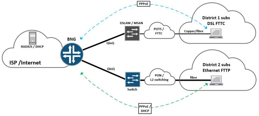
These subscribers then terminate on a BNG node on the edge of the network, which would historically have been a Cisco 7200, GSR10k, Juniper ERX or Redback router, which essentially bridges the gap between the access network and the internet.
For very large service providers with millions of subscribers this sort of approach normally works well, because their customer base is so large; it makes sense for them to provision a full-size BNG node in every town in the country and so subscribers terminate directly at the edge of the network.
However – modern BNG can be expensive. In order to provide the required throughput and features, (IPv4 / IPv6 / VPN / Quad play / QoS) it requires a significant investment in router chassis, fancy line cards and expensive licenses, at every point in the network where BNG is to be performed. For smaller ISPs this can be a deal breaker – especially if they have small chunks of subscribers dotted around.
One way of getting around this problem is to provision a centralised BNG deployment, where that function is performed somewhere centrally inside the service-provider network. Edge connectivity (PPPoE / Ethernet VLAN) is tunnelled directly from the access network, through an intermediate edge-router (U-PE) and onto a centralised BNG node where it terminates, allowing for the ISP to service a large number of subscribers from many different remote areas – using a single BNG function:
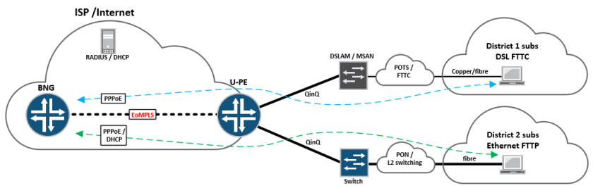
Essentially, in the above topology – the “U-PE” or access facing PE is running a standard EoMPLS LDP signalled “martini tunnel” back towards the centralised BNG router, buried deep inside the core somewhere.
The U-PE itself can be a cheaper, standard edge router, so long as it supports MPLS and LDP signalled EoMPLS tunnels – these can be provisioned anywhere on the network edge, whilst providing direct connectivity back to the BNG node at layer-2 – all this is done using PWHT (Pseudowire headend termination)
On Juniper – PWHT as a feature came into existence on, or around JUNOS version 13.1, before then there was a relatively simple “hack” that had to be performed, in order to provide the functionality. It basically involved the good ole trick of using physical loopback cables on the same device, in order to “make it work” as shown below:

This is a pretty heavy handed approach and also quite expensive – as it involves burning up expensive ports on the router, simply to bridge the gap between the access network and the subscriber termination interface.
With the PWHT feature a new type of interface is defined, known as the psuedowire service interface “PS” this is bound to a tunnel-services PIC, which essentially performs the heavy lifting.
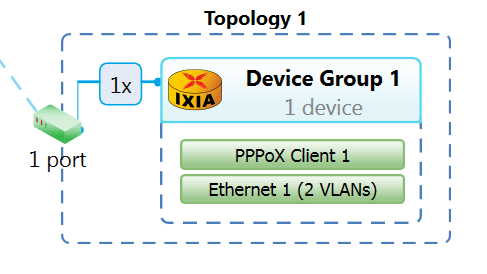
Looking at this in a lab, I have the following topology setup on an MX480 containing a MPC2E-Q and a 4x10GE MIC:

If we look at the configuration, there’s a few things we need to do – lets check out the PS interface and the l2circuit configuration:
-
tim@MX480-3> show configuration chassis
-
pseudowire-service {
-
device-count 2048;
-
}
-
fpc 1 {
-
pic 0 {
-
tunnel-services {
-
bandwidth 10g;
-
}
-
}
-
}
-
network-services enhanced-ip;
-
tim@MX480-3>
The command “pseudowire-service” basically enables the PWHT feature, and an MX chassis supports a total of 2048 pseudowire-service interfaces – each interface is bound to a l2circuit that points back to a “U-PE” edge device, that provides more than enough for most deployments,
It’s also necessary to enable tunnel-services, then when we take look at the “PS” interface, it’s easy to see how this fits together:
-
ps0 {
-
anchor-point {
-
lt-1/0/0;
-
}
-
flexible-vlan-tagging;
-
auto-configure {
-
stacked-vlan-ranges {
-
dynamic-profile vlan-prof-0 {
-
accept [ inet pppoe ];
-
ranges {
-
10-100,100-4000;
-
}
-
access-profile aaa-profile;
-
}
-
}
-
remove-when-no-subscribers;
-
}
-
mtu 1530;
-
unit 0 {
-
encapsulation ethernet-ccc;
-
}
-
}
The anchor-point statement basically binds the logical-tunnel interface directly to the PS interface, so that the “heavy lifting” can be done by the MIC, unit 0 binds directly to the l2circuit configuration – which creates the EoMPLS connectivity to the U-PE:
-
tim@MX480-3> show configuration protocols l2circuit
-
neighbor 1.1.1.2 {
-
interface ps0.0 {
-
virtual-circuit-id 10;
-
no-vlan-id-validate;
-
}
-
}
Essentially we have a standard l2circuit configuration pointing at the U-PE (the U-PE simply has a reciprocal configuration bound to it’s physical access-facing interface. Because this psuedowire will be carrying multiple VLANs (S-VLAN and C-VLAN) we don’t want to consider that information when the psuedowire is signalled, so “no-vlan-id-validate” command takes care of this.
Lets take a look at the wider BNG configuration for completeness:
-
dynamic-profiles {
-
vlan-prof-0 {
-
interfaces {
-
“$junos-interface-ifd-name” {
-
unit “$junos-interface-unit” {
-
no-traps;
-
vlan-tags outer “$junos-stacked-vlan-id” inner “$junos-vlan-id”;
-
family inet {
-
unnumbered-address lo0.0;
-
}
-
family pppoe {
-
dynamic-profile pppoe-client-profile;
-
}
-
}
-
}
-
}
-
}
-
pppoe-client-profile {
-
interfaces {
-
pp0 {
-
unit “$junos-interface-unit” {
-
no-traps;
-
ppp-options {
-
chap;
-
}
-
pppoe-options {
-
underlying-interface “$junos-underlying-interface”;
-
server;
-
}
-
keepalives interval 30;
-
family inet {
-
unnumbered-address lo0.0;
-
}
-
}
-
}
-
}
-
}
-
}
-
access {
-
radius-server {
-
192.168.3.158 {
-
port 1812;
-
accounting-port 1813;
-
secret “xxx”; ## SECRET-DATA
-
timeout 10;
-
retry 10;
-
source-address 192.168.3.54;
-
}
-
}
-
profile aaa-profile {
-
authentication-order radius;
-
radius {
-
authentication-server 192.168.3.158;
-
accounting-server 192.168.3.158;
-
options {
-
interface-description-format {
-
exclude-sub-interface;
-
}
-
nas-identifier mx5-1;
-
accounting-session-id-format decimal;
-
vlan-nas-port-stacked-format;
-
}
-
}
-
radius-server {
-
192.168.3.158 {
-
port 1812;
-
accounting-port 1813;
-
secret “xxx”; ## SECRET-DATA
-
timeout 10;
-
retry 10;
-
source-address 192.168.3.54;
-
}
-
}
-
accounting {
-
order radius;
-
accounting-stop-on-failure;
-
accounting-stop-on-access-deny;
-
immediate-update;
-
coa-immediate-update;
-
update-interval 60;
-
statistics volume-time;
-
}
-
}
-
profile no-radius-auth {
-
authentication-order none;
-
}
-
address-assignment {
-
pool Subscriber-pool {
-
family inet {
-
network 130.0.0.0/8;
-
range Sub-range-0 {
-
low 130.16.0.1;
-
high 130.31.255.255;
-
}
-
dhcp-attributes {
-
maximum-lease-time 25200;
-
}
-
}
-
}
-
}
-
}
That’s the basic configuration, lets fire up some subscribers and see what it looks like – I’m using IXIA to generate PPPoE simulated clients, we’ll start with a single double-tagged subscriber, (The S-VLAN normally represents the MSAN, the C-VLAN normally represents the subscriber’s own VLAN)
Lets check the outputs from the MX BNG:
-
tim@MX480-3> show subscribers
-
Interface IP Address/VLAN ID User Name LS:RI
-
ps0.1073761693 10 111 default:default
-
pp0.1073761694 130.16.0.3 user1@users.com default:default
-
tim@MX480-3> show subscribers detail
-
Type: VLAN
-
Logical System: default
-
Routing Instance: default
-
Interface: ps0.1073761693
-
Interface type: Dynamic
-
Underlying Interface: ps0
-
Dynamic Profile Name: vlan-prof-0
-
State: Active
-
Session ID: 19870
-
Stacked VLAN Id: 10
-
VLAN Id: 111
-
Login Time: 2016-07-10 12:34:46 UTC
-
Type: PPPoE
-
User Name: user1@users.com
-
IP Address: 130.16.0.3
-
IP Netmask: 255.255.255.255
-
Logical System: default
-
Routing Instance: default
-
Interface: pp0.1073761694
-
Interface type: Dynamic
-
Underlying Interface: ps0.1073761693
-
Dynamic Profile Name: pppoe-client-profile
-
MAC Address: 00:11:01:00:00:01
-
State: Active
-
Radius Accounting ID: 19871
-
Session ID: 19871
-
Stacked VLAN Id: 10
-
VLAN Id: 111
-
Login Time: 2016-07-10 12:34:57 UTC
-
tim@MX480-3>
So we can see the subscriber coming in, with an S-VLAN of 10 and a C-VLAN of 111, with an address handed out from the subscriber pool. Readers familiar with MX BNG will be used to using a “demux” interface, for the layer-2 side of the service, when PWHT is used – demux is replaced with the PS interface as shown in line 3.
Everything else remains the same, the subscriber layer-3 virtual interface is a “pp0” interface with an attached IP address placed into the inet routing table, this can be inserted into a routing-instance or logical-system if needed, by altering the BNG configuration and Radius config – for radius I’m using Freeradius with a basic configuration.
If we send some traffic – we should see it function end to end, and also see it on the PS0 interface:
Traffic works as expected:

Outputs from the “PS0” interface and attached subscriber units:
-
tim@MX480-3> show interfaces ps0
-
Physical interface: ps0, Enabled, Physical link is Up
-
Interface index: 154, SNMP ifIndex: 599
-
Type: Software-Pseudo, Link-level type: 90, MTU: 1530, Clocking: 1, Speed: 10000mbps
-
Device flags : Present Running
-
Interface flags: Point-To-Point Internal: 0x4000
-
Current address: dc:38:e1:fc:85:4a, Hardware address: dc:38:e1:fc:85:4a
-
Last flapped : Never
-
Input rate : 979688 bps (89 pps)
-
Output rate : 989712 bps (89 pps)
-
Logical interface ps0.0 (Index 336) (SNMP ifIndex 601)
-
Flags: Up Point-To-Point 0x4000 Encapsulation: Ethernet-CCC
-
Input packets : 5061878827
-
Output packets: 5068397825
-
Protocol ccc, MTU: 1514
-
Flags: Is-Primary
-
Logical interface ps0.32767 (Index 337) (SNMP ifIndex 600)
-
Flags: Up 0x4000 VLAN-Tag [ 0x0000.0 ] Encapsulation: ENET2
-
Input packets : 9950
-
Output packets: 0
-
Logical interface ps0.1073761693 (Index 325) (SNMP ifIndex 527)
-
Flags: Up 0x4000 VLAN-Tag [ 0x8100.10 0x8100.111 ] Encapsulation: ENET2
-
Input packets : 77850
-
Output packets: 6605
-
Protocol inet, MTU: 1508
-
Flags: Sendbcast-pkt-to-re, Unnumbered
-
Donor interface: lo0.0 (Index 322)
-
Addresses, Flags: Is-Default Is-Primary
-
Local: 1.1.1.1
-
Protocol pppoe
-
Dynamic Profile: pppoe-client-profile,
-
Service Name Table: None,
-
Max Sessions: 32000, Max Sessions VSA Ignore: Off,
-
Duplicate Protection: Off, Short Cycle Protection: Off,
-
Direct Connect: Off,
-
AC Name: MX480-3
-
tim@MX480-3>
That’s about it! PWHT is a pretty cool feature for tunnelling subscriber connectivity into a centralised BNG environment, it’s also possible to design resilient active/standby or active/active solutions by using multiple l2circuits.
It’s also worth pointing out, that provided you have the standard subscriber management licenses, no additional licenses are required to enable PWHT.
