
![]()

This is a second technical post related to segment-routing, I did a basic introduction to this technology on Juniper MX here;
https://tgregory.org/2016/08/13/segment-routing-on-junos-the-basics/
For this post I’m looking at something a bit more advanced and fun – performing Segment-routing traffic-engineering using an SDN controller, in this case OpenDaylight Beryllium – an open source SDN controller with some very powerful functionality.
This post will use Cisco ASR9kV virtual routers running on a Cisco UCS chassis, mostly because Cisco currently have the leading-edge support for Segment-routing at this time, Juniper seem to be lagging behind a bit on that front!
Lets check out the topology;
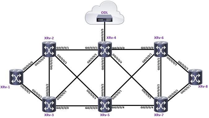
It’s a pretty simple scenario – all of the routers in the topology are configured in the following way;
- XRV-1 to XRV-8; PE routers (BGP IPv4)
- XRV 2 to XRV7; P routers (ISIS-Segment-routing)
- XRV4 is an in-path RR connecting to the ODL controller
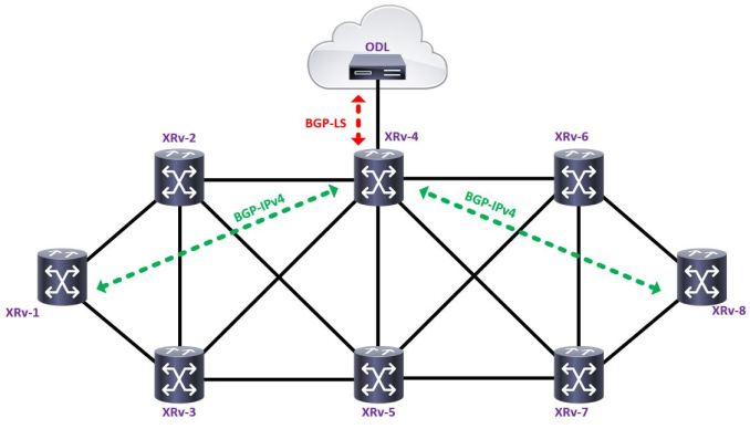
The first thing to look at here is BGP-LS “BGP Link-state” which is an extension of BGP that allows IGP information (OSPF/ISIS) to be injected into BGP, this falls conveniently into the world of centralised path computation – where we can use a controller of some sort to look at the network’s link-state information, then compute a path through the network. The controller can then communicate that path back down to a device within the network using a different method, ultimately resulting in an action of some sort – for example, signalling an LSP.
Some older historic platforms such as HP Route analytics – which enabled you to discover the live IGP topology by running ISIS or OSPF directly with a network device, however IGPs tend to be very intense protocols and also require additional effort to support within an application, rather than a traditional router. IGPs are only usually limited to the domain within which they operate – for example if we have a large network with many different IGP domains or inter-domain MPLS, the IGP’s view becomes much more limited. BGP on the other hand can bridge many of these gaps, and when programmed with the ability to carry IGP information – can be quite useful.
The next element is PCE or Path computation element – which generally contains two core elements;
- PCC – Path computation client – In the case of this lab network, a PCC would be a PE router
- PCE – Path computation element – In the case of this lab network, the PCE would be the ODL controller
These elements communicate using PCEP (Path computation element protocol) which allows a central controller (in this case ODL) to essentially program the PCC with a path – for example, by signalling the actual LSP;
Basic components;

Basic components plus an application (in this case Pathman-SR) which can compute and signal an LSP from ODL to the PCC (XRV-1);

In the above example, an opensource application (in this case Pathman-SR) is using the information about the network topology obtained via BGP-LS and PCE, stored inside ODL – to compute and signal a Segment-routing LSP from XRV-1 to XRV-8, via XRV3, XRV5 and XRV7.
Before we look at the routers, lets take a quick look at OpenDaylight, general information can be found here; https://www.opendaylight.org I’m running Beryllium 0.4.3 which is the same Cisco’s DCloud demo – it’s a relatively straightforward install process, I’m running my copy on top of a standard Ubuntu install.

From inside ODL you can use the YANG UI to query information held inside the controller, which is essentially a much easier way of querying the data, using presets – for example, I can view the link-state topology learnt via BGP-LS pretty easily;

There’s a whole load of functionality possible with ODL, from BGP-Flowspec, to Openflow, to LSP provisioning, for now we’re just going to keep it basic – all of this is opensource and requires quite a bit of “playing” to get working.
Lets take a look at provisioning some segment-routing TE tunnels, first a reminder of the diagram;

And an example of some configuration – XRv-1
ISIS;
-
router isis CORE-SR
-
is-type level-2-only
-
net 49.0001.0001.0001.00
-
address-family ipv4 unicast
-
metric-style wide
-
mpls traffic-eng level-2-only
-
mpls traffic-eng router-id Loopback0
-
redistribute static
-
segment-routing mpls
-
!
-
interface Loopback0
-
address-family ipv4 unicast
-
prefix-sid index 10
-
!
-
!
-
interface GigabitEthernet0/0/0/0.12
-
point-to-point
-
address-family ipv4 unicast
-
!
-
!
-
interface GigabitEthernet0/0/0/1.13
-
point-to-point
-
address-family ipv4 unicast
-
!
-
!
-
!
A relatively simple ISIS configuration, with nothing remarkable going on,
- Line 9 enabled Segment-Routing for ISIS
- Line 13 injects a SID (Segment-identifier) of 10 into ISIS for loopback 0
The other aspect of the configuration which generates a bit of interest, is the PCE and mpls traffic-eng configuration;
-
mpls traffic-eng
-
pce
-
peer source ipv4 49.1.1.1
-
peer ipv4 192.168.3.250
-
!
-
segment-routing
-
logging events peer-status
-
stateful-client
-
instantiation
-
!
-
!
-
logging events all
-
auto-tunnel pcc
-
tunnel-id min 1 max 99
-
!
-
reoptimize timers delay installation 0
-
!
- Line 1 enables basic traffic-engineering, an important point to note – to do MPLS-TE for Segment-routing, you don’t need to turn on TE on every single interface like you would if you were using RSVP, so long as ISIS TE is enabled and
- Lines 2, 3 and 4 connect the router from it’s loopback address, to the opendaylight controller and enable PCE
- Line 6 through 9 specify the segment-routing parameters for TE
- Line 14 specifies the tunnel ID for automatically generated tunnels – for tunnels spawned by the controller
Going back to the diagram, XRv-4 was also configured for BGP-LS;
-
router bgp 65535
-
bgp router-id 49.1.1.4
-
bgp cluster-id 49.1.1.4
-
address-family ipv4 unicast
-
!
-
address-family link-state link-state
-
!
-
neighbor 49.1.1.1
-
remote-as 65535
-
update-source Loopback0
-
address-family ipv4 unicast
-
route-reflector-client
-
!
-
!
-
neighbor 49.1.1.8
-
remote-as 65535
-
update-source Loopback0
-
address-family ipv4 unicast
-
route-reflector-client
-
!
-
!
-
neighbor 192.168.3.250
-
remote-as 65535
-
update-source GigabitEthernet0/0/0/5
-
address-family ipv4 unicast
-
route-reflector-client
-
!
-
address-family link-state link-state
-
route-reflector-client
-
!
-
!
-
!
- Line 6 enables the BGP Link-state AFI/SAFI
- Lines 8 through 19 are standard BGP RR config for IPv4
- Line 22 is the BGP peer for the Opendaylight controller
- Line 28 turns on the link-state AFI/SAFI for Opendaylight
Also of Interest on XRv-4 is the ISIS configuration;
-
router isis CORE-SR
-
is-type level-2-only
-
net 49.0001.0001.0004.00
-
distribute bgp-ls
-
address-family ipv4 unicast
-
metric-style wide
-
mpls traffic-eng level-2-only
-
mpls traffic-eng router-id Loopback0
-
redistribute static
-
segment-routing mpls
-
!
-
interface Loopback0
-
address-family ipv4 unicast
-
prefix-sid index 40
-
!
-
!
- Line 4 copies the ISIS link-state information into BGP-link state
If we do a “show bgp link-state link-state” we can see the information taken from ISIS, injected into BGP – and subsequently advertised to Opendaylight;
-
RP/0/RP0/CPU0:XRV9k-4#show bgp link-state link-state
-
Thu Dec 1 21:40:44.032 UTC
-
BGP router identifier 49.1.1.4, local AS number 65535
-
BGP generic scan interval 60 secs
-
Non-stop routing is enabled
-
BGP table state: Active
-
Table ID: 0x0 RD version: 78
-
BGP main routing table version 78
-
BGP NSR Initial initsync version 78 (Reached)
-
BGP NSR/ISSU Sync-Group versions 0/0
-
BGP scan interval 60 secs
-
Status codes: s suppressed, d damped, h history, * valid, > best
-
i – internal, r RIB-failure, S stale, N Nexthop-discard
-
Origin codes: i – IGP, e – EGP, ? – incomplete
-
Prefix codes: E link, V node, T IP reacheable route, u/U unknown
-
I Identifier, N local node, R remote node, L link, P prefix
-
L1/L2 ISIS level-1/level-2, O OSPF, D direct, S static/peer-node
-
a area-ID, l link-ID, t topology-ID, s ISO-ID,
-
c confed-ID/ASN, b bgp-identifier, r router-ID,
-
i if-address, n nbr-address, o OSPF Route-type, p IP-prefix
-
d designated router address
-
Network Next Hop Metric LocPrf Weight Path
-
*> [V][L2][I0x0][N[c65535][b0.0.0.0][s0001.0001.0001.00]]/328
-
0.0.0.0 0 i
-
*> [V][L2][I0x0][N[c65535][b0.0.0.0][s0001.0001.0002.00]]/328
-
0.0.0.0 0 i
-
*> [V][L2][I0x0][N[c65535][b0.0.0.0][s0001.0001.0003.00]]/328
-
0.0.0.0 0 i
-
*> [V][L2][I0x0][N[c65535][b0.0.0.0][s0001.0001.0004.00]]/328
-
0.0.0.0 0 i
-
*> [V][L2][I0x0][N[c65535][b0.0.0.0][s0001.0001.0005.00]]/328
-
0.0.0.0 0 i
-
*> [V][L2][I0x0][N[c65535][b0.0.0.0][s0001.0001.0006.00]]/328
-
0.0.0.0 0 i
-
*> [V][L2][I0x0][N[c65535][b0.0.0.0][s0001.0001.0007.00]]/328
-
0.0.0.0 0 i
-
*> [V][L2][I0x0][N[c65535][b0.0.0.0][s0001.0001.0008.00]]/328
-
0.0.0.0 0 i
-
*> [E][L2][I0x0][N[c65535][b0.0.0.0][s0001.0001.0001.00]][R[c65535][b0.0.0.0][s0001.0001.0002.00]][L[i10.10.12.0][n10.10.12.1]]/696
-
0.0.0.0 0 i
-
*> [E][L2][I0x0][N[c65535][b0.0.0.0][s0001.0001.0001.00]][R[c65535][b0.0.0.0][s0001.0001.0003.00]][L[i10.10.13.0][n10.10.13.1]]/696
-
0.0.0.0 0 i
-
*> [E][L2][I0x0][N[c65535][b0.0.0.0][s0001.0001.0002.00]][R[c65535][b0.0.0.0][s0001.0001.0001.00]][L[i10.10.12.1][n10.10.12.0]]/696
With this information we can use an additional app on top of OpenDaylight to provision some Segment-routing LSPs, in this case I’m going to use something from Cisco Devnet called Pathman-SR – it essentially connects to ODL using REST to program the network, Pathman can be found here; https://github.com/CiscoDevNet/pathman-sr
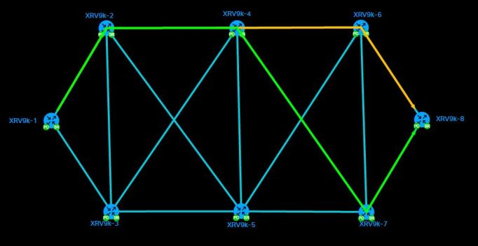
Once it’s installed and running, simply browse to it’s url (http://192.168.3.250:8020/cisco-ctao/apps/pathman_sr/index.html) and you’re presented with a nice view of the network;

From here, it’s possible to compute a path from one point to another – then signal that LSP on the network using PCEP, in this case – lets program a path from XRv9k-1 to XRv9k-8
In this case, lets program a path via XRV9k-2, via 4, via 7 to 8;

Once Pathman has calculated the path – hit deploy, Pathman sends the path to ODL – which then connects via PCEP to XRV9kv-1 and provisions the LSP;
Once this is done, it’s check XRV9k-1 to check out the SR-TE tunnel;
-
RP/0/RP0/CPU0:XRV9k-1#sh ip int bri
-
Thu Dec 1 22:05:38.799 UTC
-
Interface IP-Address Status Protocol Vrf-Name
-
Loopback0 49.1.1.1 Up Up default
-
tunnel-te1 49.1.1.1 Up Up default
-
GigabitEthernet0/0/0/0 unassigned Up Up default
-
GigabitEthernet0/0/0/0.12 10.10.12.0 Up Up default
-
GigabitEthernet0/0/0/1 unassigned Up Up default
-
GigabitEthernet0/0/0/1.13 10.10.13.0 Up Up default
-
GigabitEthernet0/0/0/2 100.1.0.1 Up Up default
-
GigabitEthernet0/0/0/3 192.168.3.248 Up Up default
-
GigabitEthernet0/0/0/4 unassigned Shutdown Down default
-
GigabitEthernet0/0/0/5 unassigned Shutdown Down default
-
GigabitEthernet0/0/0/6 unassigned Shutdown Down default
-
MgmtEth0/RP0/CPU0/0 unassigned Shutdown Down default
We can see from the output of “show ip int brief” on line 5, that interface tunnel-te1 has been created, but it’s nowhere in the config;
-
RP/0/RP0/CPU0:XRV9k-1#sh run interface tunnel-te1
-
Thu Dec 1 22:07:41.409 UTC
-
% No such configuration item(s)
-
RP/0/RP0/CPU0:XRV9k-1#
PCE signalled LSPs never appear in the configuration, they’re created, managed and deleted by the controller – it is possible to manually add an LSP then delegate it to the controller, but that’s beyond the scope here (that’s technical speak for “I couldn’t make it work 🙂 )
Lets check out the details of the SR-TE tunnel;
-
RP/0/RP0/CPU0:XRV9k-1#show mpls traffic-eng tunnels
-
Thu Dec 1 22:09:56.983 UTC
-
Name: tunnel-te1 Destination: 49.1.1.8 Ifhandle:0x8000064 (auto-tunnel pcc)
-
Signalled-Name: XRV9k-1 -> XRV9k-8
-
Status:
-
Admin: up Oper: up Path: valid Signalling: connected
-
path option 10, (Segment-Routing) type explicit (autopcc_te1) (Basis for Setup)
-
G-PID: 0x0800 (derived from egress interface properties)
-
Bandwidth Requested: 0 kbps CT0
-
Creation Time: Thu Dec 1 22:01:21 2016 (00:08:37 ago)
-
Config Parameters:
-
Bandwidth: 0 kbps (CT0) Priority: 7 7 Affinity: 0x0/0xffff
-
Metric Type: TE (global)
-
Path Selection:
-
Tiebreaker: Min-fill (default)
-
Protection: any (default)
-
Hop-limit: disabled
-
Cost-limit: disabled
-
Path-invalidation timeout: 10000 msec (default), Action: Tear (default)
-
AutoRoute: disabled LockDown: disabled Policy class: not set
-
Forward class: 0 (default)
-
Forwarding-Adjacency: disabled
-
Autoroute Destinations: 0
-
Loadshare: 0 equal loadshares
-
Auto-bw: disabled
-
Path Protection: Not Enabled
-
BFD Fast Detection: Disabled
-
Reoptimization after affinity failure: Enabled
-
SRLG discovery: Disabled
-
Auto PCC:
-
Symbolic name: XRV9k-1 -> XRV9k-8
-
PCEP ID: 2
-
Delegated to: 192.168.3.250
-
Created by: 192.168.3.250
-
History:
-
Tunnel has been up for: 00:08:37 (since Thu Dec 01 22:01:21 UTC 2016)
-
Current LSP:
-
Uptime: 00:08:37 (since Thu Dec 01 22:01:21 UTC 2016)
-
Segment-Routing Path Info (PCE controlled)
-
Segment0[Node]: 49.1.1.2, Label: 16020
-
Segment1[Node]: 49.1.1.4, Label: 16040
-
Segment2[Node]: 49.1.1.7, Label: 16070
-
Segment3[Node]: 49.1.1.8, Label: 16080
-
Displayed 1 (of 1) heads, 0 (of 0) midpoints, 0 (of 0) tails
-
Displayed 1 up, 0 down, 0 recovering, 0 recovered heads
-
RP/0/RP0/CPU0:XRV9k-1#
Points of interest;
- Line 4 shows the name of the LSP as configured by Pathman
- Line 7 shows that the signalling is Segment-routing via autoPCC
- Lines 33 and 34 show the tunnel was generated by the Opendaylight controller
- Lines 39 shows the LSP is PCE controlled
- Lines 40 through 43 show the programmed path
- Line 44 basically shows XRV9k-1 being the SR-TE headend,
Lines 40-43 show some of the main benefits of Segment-routing, we have a programmed traffic-engineered path through the network, but with far less control-plane overhead than if we’d done this with RSVP-TE, for example – lets look at the routers in the path (xrv-2 xrv-4 and xrv-7)
-
RP/0/RP0/CPU0:XRV9k-2#show mpls traffic-eng tunnels
-
Thu Dec 1 22:14:38.855 UTC
-
RP/0/RP0/CPU0:XRV9k-2#
-
RP/0/RP0/CPU0:XRV9k-4#show mpls traffic-eng tunnels
-
Thu Dec 1 22:14:45.915 UTC
-
RP/0/RP0/CPU0:XRV9k-4#
-
RP/0/RP0/CPU0:XRV9k-7#show mpls traffic-eng tunnels
-
Thu Dec 1 22:15:17.873 UTC
-
RP/0/RP0/CPU0:XRV9k-7#
Essentially – the path that the SR-TE tunnel takes contains no real control-plane state, this is a real advantage for large networks as the whole thing is much more efficient.
The only pitfall here, is that whilst we’ve generated a Segment-routed LSP, like all MPLS-TE tunnels we need to tell the router to put traffic into it – normally we do this with autoroute-announce or a static route, at this time OpenDaylight doesn’t support the PCEP extensions to actually configure a static route, so we still need to manually put traffic into the tunnel – this is fixed in Cisco’s openSDN and WAE (wan automation engine)
-
router static
-
address-family ipv4 unicast
-
49.1.1.8/32 tunnel-te1
-
!
-
!
I regularly do testing and development work with some of the largest ISPs in the UK – and something that regularly comes up, is where customers are running a traditional full-mesh of RSVP LSPs, if you have 500 edge routers – that’s 250k LSPs being signalled end to end, the “P” routers in the network need to signal and maintain all of that state. When I do testing in these sorts of environments, it’s not uncommon to see nasty problems with route-engine CPUs when links fail, as those 250k LSPs end up having to be re-signalled – indeed this very subject came up in a conversation at LINX95 last week.
With Segment-routing, the traffic-engineered path is basically encoded into the packet with MPLS labels – the only real difficulty is that it requires the use of more labels in the packet, but once the hardware can deal with the label-depth, I think it’s a much better solution than RSVP, it’s more efficient and it’s far simpler.
From my perspective – all I’ve really shown here is a basic LSP provisioning tool, but it’s nice to be able to get the basics working, in the future I hope to get my hands on a segment-routing enabled version of Northstar, or Cisco’s OpenSDN controller – (which is Cisco productised version of ODL) 🙂

Another super article! Getting ODL up and running for this has been on my list for a while, I’ll take this as a push to get the finger out 🙂
LikeLike
Thanks! it’s actually a really powerful platform – it’s just very much in “kit form” at the moment and it’s very open source, but it has a heck of a lot of functionality,
LikeLike
hi, it is an excellent article, could you please share the all configuration of each router?
LikeLiked by 1 person
Excellent article Tim…Thank you!
Can you please provide some details on how to set up the lab? Eg GNS3 VM / EVE-NG / VIRL etc? GNS3 VM works, but VNC response is very slow.
LikeLike