I’ve been doing quite a lot of MX BNG stuff this year, so I thought I’d run through another quite flexible way of terminating broadband subscribers onto a Juniper MX router.
The feature is called Psuedowire headend termination, “PWHT” or simply Psuedowire head-end “PWHE” depending on whether you work for Cisco or Juniper 😉 but it essentially solves a relatively simple problem.
In traditional broadband designs – especially in DSL “FTTC” or Fibre Ethernet “FTTP” we’re used to seeing large numbers of subscribers, connecting into the ISP edge at layer-2 with PPPoE or plain Ethernet. This is normally performed with VLANS, either via an MSAN (DSL/FTTC) or as is the case with Ethernet FTTP subscribers – a plain switched infrastructure or some form of passive-optical (PON/GPON) presentation:
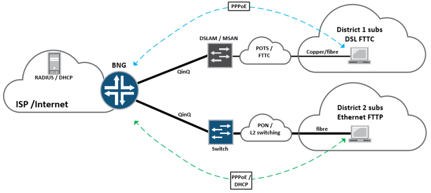
These subscribers then terminate on a BNG node on the edge of the network, which would historically have been a Cisco 7200, GSR10k, Juniper ERX or Redback router, which essentially bridges the gap between the access network and the internet.
For very large service providers with millions of subscribers this sort of approach normally works well, because their customer base is so large; it makes sense for them to provision a full-size BNG node in every town in the country and so subscribers terminate directly at the edge of the network.
However – modern BNG can be expensive. In order to provide the required throughput and features, (IPv4 / IPv6 / VPN / Quad play / QoS) it requires a significant investment in router chassis, fancy line cards and expensive licenses, at every point in the network where BNG is to be performed. For smaller ISPs this can be a deal breaker – especially if they have small chunks of subscribers dotted around.
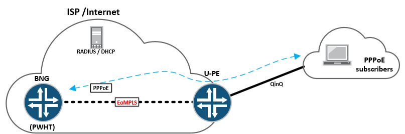
One way of getting around this problem is to provision a centralised BNG deployment, where that function is performed somewhere centrally inside the service-provider network. Edge connectivity (PPPoE / Ethernet VLAN) is tunnelled directly from the access network, through an intermediate edge-router (U-PE) and onto a centralised BNG node where it terminates, allowing for the ISP to service a large number of subscribers from many different remote areas – using a single BNG function:
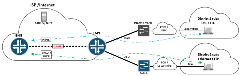
Essentially, in the above topology – the “U-PE” or access facing PE is running a standard EoMPLS LDP signalled “martini tunnel” back towards the centralised BNG router, buried deep inside the core somewhere.
The U-PE itself can be a cheaper, standard edge router, so long as it supports MPLS and LDP signalled EoMPLS tunnels – these can be provisioned anywhere on the network edge, whilst providing direct connectivity back to the BNG node at layer-2 – all this is done using PWHT (Pseudowire headend termination)
On Juniper – PWHT as a feature came into existence on, or around JUNOS version 13.1, before then there was a relatively simple “hack” that had to be performed, in order to provide the functionality. It basically involved the good ole trick of using physical loopback cables on the same device, in order to “make it work” as shown below:
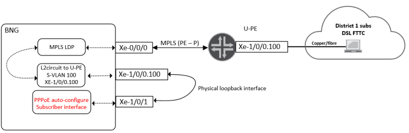
This is a pretty heavy handed approach and also quite expensive – as it involves burning up expensive ports on the router, simply to bridge the gap between the access network and the subscriber termination interface.
With the PWHT feature a new type of interface is defined, known as the psuedowire service interface “PS” this is bound to a tunnel-services PIC, which essentially performs the heavy lifting.
Looking at this in a lab, I have the following topology setup on an MX480 containing a MPC2E-Q and a 4x10GE MIC:
If we look at the configuration, there’s a few things we need to do – lets check out the PS interface and the l2circuit configuration:
-
tim@MX480-3> show configuration chassis
-
pseudowire-service {
-
device-count 2048;
-
}
-
fpc 1 {
-
pic 0 {
-
tunnel-services {
-
bandwidth 10g;
-
}
-
}
-
}
-
network-services enhanced-ip;
-
tim@MX480-3>
The command “pseudowire-service” basically enables the PWHT feature, and an MX chassis supports a total of 2048 pseudowire-service interfaces – each interface is bound to a l2circuit that points back to a “U-PE” edge device, that provides more than enough for most deployments,
It’s also necessary to enable tunnel-services, then when we take look at the “PS” interface, it’s easy to see how this fits together:
-
ps0 {
-
anchor-point {
-
lt-1/0/0;
-
}
-
flexible-vlan-tagging;
-
auto-configure {
-
stacked-vlan-ranges {
-
dynamic-profile vlan-prof-0 {
-
accept [ inet pppoe ];
-
ranges {
-
10-100,100-4000;
-
}
-
access-profile aaa-profile;
-
}
-
}
-
remove-when-no-subscribers;
-
}
-
mtu 1530;
-
unit 0 {
-
encapsulation ethernet-ccc;
-
}
-
}
The anchor-point statement basically binds the logical-tunnel interface directly to the PS interface, so that the “heavy lifting” can be done by the MIC, unit 0 binds directly to the l2circuit configuration – which creates the EoMPLS connectivity to the U-PE:
-
tim@MX480-3> show configuration protocols l2circuit
-
neighbor 1.1.1.2 {
-
interface ps0.0 {
-
virtual-circuit-id 10;
-
no-vlan-id-validate;
-
}
-
}
Essentially we have a standard l2circuit configuration pointing at the U-PE (the U-PE simply has a reciprocal configuration bound to it’s physical access-facing interface. Because this psuedowire will be carrying multiple VLANs (S-VLAN and C-VLAN) we don’t want to consider that information when the psuedowire is signalled, so “no-vlan-id-validate” command takes care of this.
Lets take a look at the wider BNG configuration for completeness:
-
dynamic-profiles {
-
vlan-prof-0 {
-
interfaces {
-
“$junos-interface-ifd-name” {
-
unit “$junos-interface-unit” {
-
no-traps;
-
vlan-tags outer “$junos-stacked-vlan-id” inner “$junos-vlan-id”;
-
family inet {
-
unnumbered-address lo0.0;
-
}
-
family pppoe {
-
dynamic-profile pppoe-client-profile;
-
}
-
}
-
}
-
}
-
}
-
pppoe-client-profile {
-
interfaces {
-
pp0 {
-
unit “$junos-interface-unit” {
-
no-traps;
-
ppp-options {
-
chap;
-
}
-
pppoe-options {
-
underlying-interface “$junos-underlying-interface”;
-
server;
-
}
-
keepalives interval 30;
-
family inet {
-
unnumbered-address lo0.0;
-
}
-
}
-
}
-
}
-
}
-
}
-
access {
-
radius-server {
-
192.168.3.158 {
-
port 1812;
-
accounting-port 1813;
-
secret “xxx”; ## SECRET-DATA
-
timeout 10;
-
retry 10;
-
source-address 192.168.3.54;
-
}
-
}
-
profile aaa-profile {
-
authentication-order radius;
-
radius {
-
authentication-server 192.168.3.158;
-
accounting-server 192.168.3.158;
-
options {
-
interface-description-format {
-
exclude-sub-interface;
-
}
-
nas-identifier mx5-1;
-
accounting-session-id-format decimal;
-
vlan-nas-port-stacked-format;
-
}
-
}
-
radius-server {
-
192.168.3.158 {
-
port 1812;
-
accounting-port 1813;
-
secret “xxx”; ## SECRET-DATA
-
timeout 10;
-
retry 10;
-
source-address 192.168.3.54;
-
}
-
}
-
accounting {
-
order radius;
-
accounting-stop-on-failure;
-
accounting-stop-on-access-deny;
-
immediate-update;
-
coa-immediate-update;
-
update-interval 60;
-
statistics volume-time;
-
}
-
}
-
profile no-radius-auth {
-
authentication-order none;
-
}
-
address-assignment {
-
pool Subscriber-pool {
-
family inet {
-
network 130.0.0.0/8;
-
range Sub-range-0 {
-
low 130.16.0.1;
-
high 130.31.255.255;
-
}
-
dhcp-attributes {
-
maximum-lease-time 25200;
-
}
-
}
-
}
-
}
-
}
That’s the basic configuration, lets fire up some subscribers and see what it looks like – I’m using IXIA to generate PPPoE simulated clients, we’ll start with a single double-tagged subscriber, (The S-VLAN normally represents the MSAN, the C-VLAN normally represents the subscriber’s own VLAN)

Lets check the outputs from the MX BNG:
-
tim@MX480-3> show subscribers
-
Interface IP Address/VLAN ID User Name LS:RI
-
ps0.1073761693 10 111 default:default
-
pp0.1073761694 130.16.0.3 user1@users.com default:default
-
tim@MX480-3> show subscribers detail
-
Type: VLAN
-
Logical System: default
-
Routing Instance: default
-
Interface: ps0.1073761693
-
Interface type: Dynamic
-
Underlying Interface: ps0
-
Dynamic Profile Name: vlan-prof-0
-
State: Active
-
Session ID: 19870
-
Stacked VLAN Id: 10
-
VLAN Id: 111
-
Login Time: 2016-07-10 12:34:46 UTC
-
Type: PPPoE
-
User Name: user1@users.com
-
IP Address: 130.16.0.3
-
IP Netmask: 255.255.255.255
-
Logical System: default
-
Routing Instance: default
-
Interface: pp0.1073761694
-
Interface type: Dynamic
-
Underlying Interface: ps0.1073761693
-
Dynamic Profile Name: pppoe-client-profile
-
MAC Address: 00:11:01:00:00:01
-
State: Active
-
Radius Accounting ID: 19871
-
Session ID: 19871
-
Stacked VLAN Id: 10
-
VLAN Id: 111
-
Login Time: 2016-07-10 12:34:57 UTC
-
tim@MX480-3>
So we can see the subscriber coming in, with an S-VLAN of 10 and a C-VLAN of 111, with an address handed out from the subscriber pool. Readers familiar with MX BNG will be used to using a “demux” interface, for the layer-2 side of the service, when PWHT is used – demux is replaced with the PS interface as shown in line 3.
Everything else remains the same, the subscriber layer-3 virtual interface is a “pp0” interface with an attached IP address placed into the inet routing table, this can be inserted into a routing-instance or logical-system if needed, by altering the BNG configuration and Radius config – for radius I’m using Freeradius with a basic configuration.
If we send some traffic – we should see it function end to end, and also see it on the PS0 interface:
Traffic works as expected:

Outputs from the “PS0” interface and attached subscriber units:
-
tim@MX480-3> show interfaces ps0
-
Physical interface: ps0, Enabled, Physical link is Up
-
Interface index: 154, SNMP ifIndex: 599
-
Type: Software-Pseudo, Link-level type: 90, MTU: 1530, Clocking: 1, Speed: 10000mbps
-
Device flags : Present Running
-
Interface flags: Point-To-Point Internal: 0x4000
-
Current address: dc:38:e1:fc:85:4a, Hardware address: dc:38:e1:fc:85:4a
-
Last flapped : Never
-
Input rate : 979688 bps (89 pps)
-
Output rate : 989712 bps (89 pps)
-
Logical interface ps0.0 (Index 336) (SNMP ifIndex 601)
-
Flags: Up Point-To-Point 0x4000 Encapsulation: Ethernet-CCC
-
Input packets : 5061878827
-
Output packets: 5068397825
-
Protocol ccc, MTU: 1514
-
Flags: Is-Primary
-
Logical interface ps0.32767 (Index 337) (SNMP ifIndex 600)
-
Flags: Up 0x4000 VLAN-Tag [ 0x0000.0 ] Encapsulation: ENET2
-
Input packets : 9950
-
Output packets: 0
-
Logical interface ps0.1073761693 (Index 325) (SNMP ifIndex 527)
-
Flags: Up 0x4000 VLAN-Tag [ 0x8100.10 0x8100.111 ] Encapsulation: ENET2
-
Input packets : 77850
-
Output packets: 6605
-
Protocol inet, MTU: 1508
-
Flags: Sendbcast-pkt-to-re, Unnumbered
-
Donor interface: lo0.0 (Index 322)
-
Addresses, Flags: Is-Default Is-Primary
-
Local: 1.1.1.1
-
Protocol pppoe
-
Dynamic Profile: pppoe-client-profile,
-
Service Name Table: None,
-
Max Sessions: 32000, Max Sessions VSA Ignore: Off,
-
Duplicate Protection: Off, Short Cycle Protection: Off,
-
Direct Connect: Off,
-
AC Name: MX480-3
-
tim@MX480-3>
That’s about it! PWHT is a pretty cool feature for tunnelling subscriber connectivity into a centralised BNG environment, it’s also possible to design resilient active/standby or active/active solutions by using multiple l2circuits.
It’s also worth pointing out, that provided you have the standard subscriber management licenses, no additional licenses are required to enable PWHT.

Another really good post, thanx! Maybe an odd question, but can I ask what software / iconset you use for your diagrams?
LikeLike
Thanks! I actually got them from here; http://www.slideshare.net/JuniperJapan/juniper-icons click on the download button and it should give you the full powerpoint with all the Icons – you can also copy and paste them into Visio 🙂
LikeLike
Hi Tim,
Can you please tell us what JunOS versions you are running for this lab as we have some problems terminating the subscribers into the BNG via the PE.
Thank you and keep up the good work!
LikeLike
Hi Victor, this particular lab was done on “14.1X50-D135.1” however you should be able to get it working with any of the recent Occam/Tomcat releases, I currently have subscriber-termination functioning on “15.1R4.6” for a customer, so you should be ok with either of those two, however if you’re using a “low end” device such as an MX80 or MX104, you’ll need an “X” release of code, but if you’re using something bigger, 15.1R4.6 should work fine.
LikeLike
Thank you for replying back, we may have to try with a different firmware as we are using a mx10-t with Junos: 15.1F6.9 for BNG and I think we’ve tried with 15.1R4.6 too and for the PE we’re using an MX80 Junos: 12.1R6.5, but this one should not impact anything.
Our setup it’s a little bit different as we are trying to connect the same PE to two BNG’s.
LikeLike
From what I can remember, if you’re trying to do subscriber termination on anything below an MX240, you need an “X” release of PPC code, such as jinstall-ppc-14.1X50-D130.3-domestic-signed.tgz
LikeLike
Hi Tim,
Thanks for the amazing article.
Can You confirm that the same VLAN tags (VLAN-S / C-VLAN) can be configured in different access nodes and PWHT concept will continue to be applicable?
Thank you and keep up the good work
LikeLike
Hi, I haven’t actually tried this with PWHT but it should work – where you have the same SVLAN / CVLAN combination, on each Pseudowire to each access-node, I’d recommending checking with Juniper or doing your own test first – but I’m 90% sure it’ll work 🙂
LikeLike
Hi Tim, nice writeup.
do you have the full set commands for this? for example I don’t understand the logic of the inner/outer vlans applicable where and what profile relates to which customer?
Likewise no config for the physical interface binding to the ps0 interface, just need things black and white a little
LikeLike
Hi Tony,
In this example, under the ps0 interface, the “stacked-vlan ranges” of 10-100, means that anything tagged with say Vlan 11, is the S-VLAN of Vlan-11, this could represent an entire MSAN or DSLAM, we then have the C-VLAN range of 100-4000, which would mean that anything tagged with a S-VLAN of 11, could have any number of C-VLANs between 100 and 4000 (3900 customers on Vlan 11) and I can increment the S-VLAN of 11, all the way up to 100, giving me a very large number of subscribers (number of S vlans, multiplied by the number of C vlans)
Regarding the ps0 interface, there is no physical binding between the ps0 and a specific physical interface – because it’s done internally using “psuedowire-service” under the chassis configuration. Basically – the MSAN edge router runs a Pseudowire directly to the PWHT node (from this example) which simply terminates on the PWHT loopback interface. Provided it’s using the correct PW-ID the Psuedowire will come up, all the edge node needs to do is send correctly tagged frames to the PWHT node – because PPPoE is switched on, on the ps0 interface – it should automatically work, because the traffic is automatically tunnelled from the MPLS core IP interface, to the ps0 interface inside the router. (this eliminates the need to do the Vlan-looparound hack)
Hope this clears it up 🙂
PS – I uploaded the entire config for you, from this example 🙂
http://pastebin.com/K3j6MNuY
LikeLike
him tim, thank will review it.
what does ip lo0.0 unnumbered refer too?
LikeLike
Hi Tony,
The lo0.0 address is an unnumbered address that’s used as the IPv4 gateway for each of the DHCP subscribers – basically it has to be there otherwise the host has no gateway (even though it’s the same address 😉 ) I wish Juniper would hide it, or just make it a default,
LikeLike
*hi
*thanks
LikeLike
thanks for replying so quick Tim.
ok this must be ppp not the same subnet magic (got me before)!
as you’re lo0.0 is 1.1.1.1/32 whilst you’re dhcp scope is in the 130.0.0.0/8 range
LikeLike
Hi Tim, can you help me t-shoot, I can see PPPoE Discovery packets hitting the BNG but the BNG not doing anything with them, I’ve set a traceoption on protocol pppoe for everything and nothing seems to happen, a packet capture confirms the BNG is getting the PADI
LikeLike
I’ve left my paste of my config here including license.
http://pastebin.com/uZWzBxyj
LikeLike
Hi Tony,
The first thing that might help here is the Junos version 16.1 is pretty new – the newest I normally recommend to my customers is 15.1R5 – which is an OCCAM release (re-built with broadband optimised code) the second thing is that after 15.1R4 Juniper introduced a feature known as “enhanced subscriber management” which means you actually have to “switch on” the subscriber management functionality, follow the steps in this link – and it might do the trick (although I haven’t tried this on 16.1 – it should still apply)
https://www.juniper.net/techpubs/en_US/junos/topics/task/configuration/subscriber-management-enhanced-initial-setup.html
Try that first, let me know if it does/doesn’t work,
Cheers 🙂
LikeLiked by 1 person
Cheers for replying Tim.
Ok done that, rebooted, from traceoptions I’m getting the following
Jan 16 11:20:07.039218 removeMajorInterface: UIFL not found: demux0.2147483661
Jan 16 11:20:20.861398 eraStartEvent: eraStartEvents=14
Jan 16 11:20:21.440719 eraStopEvent: eraStopEvents=14
Jan 16 11:20:28.120990 removeMajorInterface: UIFL not found: demux0.2147483662
Jan 16 11:20:54.802026 eraStartEvent: eraStartEvents=15
Jan 16 11:21:00.147336 eraStopEvent: eraStopEvents=15
seems like it’s looking for a demux interface logical?
PADI’s are still incoming
LikeLike
Hi Tony,
I found 3x small differences in your config;
1 – You “access-profile aaa-profile” isn’t applied to the main router configuration,
2 – the the same profile is applied in the wrong place under the ps0 interface, it should be under your “dsl-fttc-subscribers” stanza, not under the “stacked-vlan-ranges” stanza”
3- “auto-configuration” needs turning on under the system configuration,
Cheers
Tim,
LikeLiked by 1 person
On point one, I can see it’s applied to the main router config per below:
access {
}
}
profile aaa-profile {
authentication-order radius;
radius {
authentication-server 192.168.1.45;
accounting-server 192.168.1.45;
options {
interface-description-format {
exclude-sub-interface;
}
nas-identifier vMX-vBNG;
accounting-session-id-format decimal;
vlan-nas-port-stacked-format;
}
}
On point two, I don’t get this option under the dynamic-profile !?
root@vMX-VCP-vBNG# …lan-ranges dynamic-profile dsl-fttc-subscribers ?
Possible completions:
+ accept Configure accepted packet types
+ apply-groups Groups from which to inherit configuration data
+ apply-groups-except Don’t inherit configuration data from these groups
> ranges Configure interface based on stacked-vlan range
[edit]
on point 3 added.
LikeLike
Hi Tony, the “access-profile aaa-profile” is defined correctly under the access stanza, but it also must be applied to the main configuration, see the examdiff screenshot of my config on the left, and yours on the right;
That should also fix the interface flapping, you’ll need to make sure you Radius is 100% as this part of the config tells the router to fire the RADIUS request
LikeLiked by 1 person
Ok getting some traction now, getting the following toggling from 0 or 1 subscribers
root@vMX-VCP-vBNG# run show subscribers
Interface IP Address/VLAN ID User Name LS:RI
ps0.3221225580 0x8100.4000 0x8100.10 default:default
IOS dialer is bouncing, seeing PADT’s from my client
Client-ISR#
*Jan 16 23:37:52.893: %DIALER-6-BIND: Interface Vi2 bound to profile Di1
Client-ISR#
*Jan 16 23:37:52.896: %LINK-3-UPDOWN: Interface Virtual-Access2, changed state to up
*Jan 16 23:37:53.095: %DIALER-6-UNBIND: Interface Vi2 unbound from profile Di1
Client-ISR#
*Jan 16 23:37:53.098: %LINK-3-UPDOWN: Interface Virtual-Access2, changed state to down
LikeLike
Hi Tim, ok great added that, but still don’t get the option to add my access-profile behind the dynamic-profile under interface ps0
I have seen the RADIUS request now, so I’m wondering I actually need the access-profile at all?
I will work on my RAIDIUS config now, really appreciate the support buddy!
LikeLiked by 1 person
Just out of interest is their any way to authenticate the users directly on the BNG that Junos offers
LikeLike
By the way apologies for adding so many comments, although I don’t get the option with a reply button directly below you’re comments.
LikeLike
Hi Tim,
Ok so my RADIUS passes the authentication i see from it’s logs
Radius authentication passed for USER: tony@netsource.net MAC: AUTHTYPE:
but when I look at the traceoptions on vMX it seems to assign an address but subscribers is still blank
Jan 18 13:08:52.934363 *********************************************************
Jan 18 13:08:52.934373 IPV4 ADDRESS ALLOC begin
Jan 18 13:08:52.934385 Just get the first pool with addresses
Jan 18 13:08:52.934397 NetworkMatch: Found a pool subscriber-pool
Jan 18 13:08:52.934410 NetworkMatch: calling addressGetNext for pool ‘subscriber-pool’
Jan 18 13:08:52.934422 No host is found
Jan 18 13:08:52.934498 Searching for available address in range low-high, low=168.254.34.2, high=168.254.34.254, next=168.254.34.20 session-id:240
Jan 18 13:08:52.934523 IPV6 ADDRESS ALLOC begin
Jan 18 13:08:52.934534 IPV6 PREFIX ALLOC begin
Jan 18 13:08:52.934544 ****************** END-NetworkMatch *********************
Jan 18 13:08:52.934555 DUMP of all addressRequest fields for subscriber session-id:240 router default:default
Jan 18 13:08:52.934570 client type jpppd-client client type 64 mac address 50:00:00:07:00:00
Jan 18 13:08:52.934585 REQUESTING: OldStyle 0 OldStyleFilled 1 hint null network 255.255.255.254 client pool name
Jan 18 13:08:52.934605 V4NA: req: yes pool: subscriber-pool address: 168.254.34.20
Jan 18 13:08:52.934618 V6NA: req: no pool: NULL address: null
Jan 18 13:08:52.934632 V6PD: req: no pool: NULL prefix: null/0
Jan 18 13:08:52.934646 V6NDRA: req: no pool: NULL ndra prefix: null/0
Jan 18 13:08:52.934657 *********************************************************
Jan 18 13:08:52.934668 Done processing rules
Jan 18 13:08:52.934687 Pool::addressAssign: pool subscriber-pool addr 168.254.34.20 range 168.254.34.2 session-id:240
Jan 18 13:08:52.934707 Pool::addressAssign: pool subscriber-pool addr 168.254.34.20 range 168.254.34.2 returning session-id:240
Jan 18 13:08:52.934827 Trying to assign address 168.254.34.20 to subscriber session-id:240
Jan 18 13:08:52.934960 Inserting address 168.254.34.20 for session-id:240 into pool subscriber-pool
Jan 18 13:08:52.934993 Finding a client snapshot session-id:240
Jan 18 13:08:52.935045 Result have been returned with opcode=0, result=2
Jan 18 13:08:52.935058 ************* Results of Address Allocation *************
Jan 18 13:08:52.935070 DUMP of all addressRequest fields for subscriber session-id:240 router default:default
Jan 18 13:08:52.935086 client type jpppd-client client type 64 mac address 50:00:00:07:00:00
Jan 18 13:08:52.935100 REQUESTING: OldStyle 0 OldStyleFilled 1 hint null network 255.255.255.254 client pool name
Jan 18 13:08:52.935112 Framed-Pool–>SDB_USER_IP_POOL ‘subscriber-pool’ used for V4NA
Jan 18 13:08:52.935136 V4NA: req: yes pool: subscriber-pool address: 168.254.34.20
Jan 18 13:08:52.935150 V6NA: req: no pool: NULL address: null
Jan 18 13:08:52.935165 V6PD: req: no pool: NULL prefix: null/0
Jan 18 13:08:52.935325 V6NDRA: req: no pool: NULL ndra prefix: null/0
Jan 18 13:08:52.935342 *********************************************************
Jan 18 13:08:52.935359 authd_auth_update_local_server_address ::Searching access profile aaa-profile for local DNS Server
Jan 18 13:08:52.935381 AuthFsm::current state=AuthStart(1) event=2 astEntry=0x99f706c aaa msg=0x98f2b44 session-id:240
Jan 18 13:08:52.935437 Auth-FSM: Process Auth-Response for session-id:240 and client type broadband
Jan 18 13:08:52.935452 createDynamicRequest: (2) received
Jan 18 13:08:52.935465 CoARequest CTOR 0x0x9a0aa6c
Jan 18 13:08:52.935484 ServiceAtLoginRequest::validateRequest
Jan 18 13:08:52.935499 Framework: auth result is 1. Performing post-auth operations
Jan 18 13:08:52.935512 Set Idle Timeout Ingress Only: FALSE
Jan 18 13:08:52.935522 Framework: result is 1.
Jan 18 13:08:52.935537 SEQ SendClientMsg:jpppd-client session-id:240 reply-code=1 (OK), result-subopcode=1 (ACCESS_OK), cookie=358, rply_len=28, num_tlv_blocks=0
Jan 18 13:08:52.935556 authd_auth_aaa_msg_destructauth_aaa_msg: 0x98f25d8
Jan 18 13:08:52.935625 ###################################################################
Jan 18 13:08:52.935642 ######################### AUTH REQ ACK SENT #######################
Jan 18 13:08:52.935652 ###################################################################
Jan 18 13:08:52.935668 Auth-FSM: GRES-Mirror for session-id:240 state:AuthClntRespWait(4)
Jan 18 13:08:52.935683 doPersistedDataUpdates
Jan 18 13:08:52.935694 persistOnlyPrivateData m_inFlight
root@vMX-VCP-vBNG# run show subscribers
Total subscribers: 0, Active Subscribers: 0
I hav’nt added any specific Radius attributes to the authorization profile, not sure if you did?
I still don’t have the option to add my access-profile behind the dynamic-profile under interface ps0 , did you see this?
root@vMX-VCP-vBNG# …lan-ranges dynamic-profile dsl-fttc-subscribers ?
Possible completions:
+ accept Configure accepted packet types
+ apply-groups Groups from which to inherit configuration data
+ apply-groups-except Don’t inherit configuration data from these groups
> ranges Configure interface based on stacked-vlan range
LikeLike
thought i’d update you Tim, I managed to get this working by changing my IOS dialer1 config from “ip address dhcp” to “ip address negotiated”
now I get two host routes in the IOS route table the .1 lo0.0 from BNG and one from the pool host address assigned to dialer1 but no default gateway set, in IOS as client/server if using DHCP as the negotiated address from the client I can get the default gateway dynamically.
I tried “set access address-assignment pool subscriber-pool family inet dhcp-attributes router 168.254.34.1” but still not doing it
I don’t think Junos is actually using the DHCP functions here, as when I configured “ip address dhcp” on the IOS client , Junos doesn’t seem to play ball in the LCP phase where with negotiated it does. (if I do dhcp server options on IOS client/server combo , I do get the default gateway sent to me)
So I just had to set the 0/0 manually to the dialer on IOS, in Juniper KB’s they do set the static route manually if I was using a Junos device as the client anyway it seems, let me know if their’s a way to get the default gateway set automatically.
have you got any thoughts about scaling a HQoS policy to enforce egress shapers and ingress policers per subscriber and where this should be applied, I’d imagine the BNG ps0.x IFL’s right, as the uPE might be low end devices without the E or EQ MPC’s
LikeLike
Hi Tony, Apologies I’ve not replied – I’ve been very busy these last few days or so (and still am unfortunately) Regarding QoS – correct, the uPE can just be a low-end device, so long as it can create a Pseudowire back to the BNG it shouldn’t need much else.. On the BNG itself, we usually use MPC2-Q or EQ cards for 128k/512k queues, this gives you plenty – the scaling values for 15.1 can be found here; https://www.juniper.net/techpubs/en_US/release-independent/junos/information-products/pathway-pages/subscriber-access/subscriber-management-scaling-values-enhanced.xls
Also – this obviously applies to physical hardware, I haven’t seen anyone do this “in anger” on vMX yet, so I’m not sure how it’d hold up,
LikeLiked by 1 person
thanks Tim, few points:
the dhcp config is not required as the lease will not be sent with an ipcp negotiated address.
on qos, what I meant was Raidus attributes effectively, I’m in the middle of doing this right now so that the qos policies are applied to the pp0.x interfaces as I don’t think doing this manually is feasible, will let you know if I get success.
great link by the way, shame they don’t cover the full set of MPC/DPC’s – there are huge gotchas per line card/or chassis on this, so recommend getting a Juniper SE involved at the start.
LikeLike
Tim, is their any chance you could send me an email please? i’d really like you’re advice on a few things please.
my email is mothafungla@gmail.com
LikeLike
hi i need help
i configure juniper my Mx960 equipment of this example. But does not work.
my configuration
DYNAMIC-PPPOE-PROFILE {
routing-instances {
“$junos-routing-instance” {
interface “$junos-interface-name”;
inactive: routing-options {
access-internal {
route $junos-subscriber-ip-address {
qualified-next-hop “$junos-interface-name”;
}
}
}
}
}
interfaces {
pp0 {
unit “$junos-interface-unit” {
no-traps;
ppp-options {
pap;
}
pppoe-options {
underlying-interface “$junos-underlying-interface”;
server;
}
keepalives interval 15;
family inet {
filter {
input next-hop;
output SHAPE;
}
unnumbered-address “$junos-loopback-interface”;
}
}
}
}
}
DYNAMIC-VLAN-PWHT {
interfaces {
“$junos-interface-ifd-name” {
unit “$junos-interface-unit” {
no-traps;
proxy-arp unrestricted;
vlan-id “$junos-vlan-id”;
demux-options {
underlying-interface “$junos-interface-ifd-name”;
}
family pppoe {
dynamic-profile DYNAMIC-PPPOE-PROFILE;
service-name-table PPPoE-INET;
}
}
}
}
}
show interfaces ps0
anchor-point {
lt-8/2/0;
}
flexible-vlan-tagging;
auto-configure {
vlan-ranges {
dynamic-profile DYNAMIC-VLAN-PWHT {
accept pppoe;
ranges {
any;
}
}
access-profile CITRadius;
}
remove-when-no-subscribers;
}
mtu 2500;
mac 00:11:22:33:44:55;
unit 0 {
encapsulation ethernet-ccc;
}
equipment come PADI packets but does not send PADO packets.
Whats problem?
LikeLike
This is a great article.
I have been doing thins for a while, but was wondering if it is at all possible to get a VPLS domain to join ps0.
If you have any pointers on how to do this without a loopback cable, I would really appreciate it.
LikeLike
VPLS into L2circuit was actually pretty easy. I am posting this here as it might help someone else.
I am using lt-0/0/0.553 as the link from vpls to the l2circuit.
interfaces {
lt-0/0/0 {
unit 553 {
encapsulation ethernet-vpls;
peer-unit 10553;
}
unit 10553 {
encapsulation ethernet-ccc;
peer-unit 553;
}
}
ps1 {
anchor-point {
lt-0/0/0;
}
flexible-vlan-tagging;
auto-configure {
stacked-vlan-ranges {
dynamic-profile DEMUX-STACKED-VLAN-PPPoE {
accept pppoe;
ranges {
2-4094,1-4094;
}
}
access-profile PPPoE;
}
vlan-ranges {
dynamic-profile VLAN-PPPoE {
accept pppoe;
ranges {
2-4094;
}
}
access-profile PPPoE;
}
remove-when-no-subscribers;
}
mtu 9100;
mac 00:66:77:88:99:f1;
no-gratuitous-arp-request;
unit 0 {
encapsulation ethernet-ccc;
}
}
}
protocols {
l2circuit {
local-switching {
interface lt-0/0/0.10553 {
end-interface {
interface ps1.0;
}
ignore-encapsulation-mismatch;
ignore-mtu-mismatch;
}
}
}
}
routing-instances {
VPLS-CORE-VSI-PPPOE {
instance-type vpls;
interface lt-0/0/0.553;
route-distinguisher 1.1.1.1:553;
vrf-target target:111111:553;
protocols {
vpls {
control-word;
no-tunnel-services;
site rtr1-xxxx {
site-identifier 2;
}
ignore-encapsulation-mismatch;
}
}
}
}
LikeLike
Hi Paul,
What’s the use-case as you’ve placed the services into a vpls ri?
Can other Ethernet based sites get BUM/Unicast frames to the subscriber?
I can understand placing the service into a RI VRF so that the L3 service become apart of a VPN for anywhere-to-anywhere requirements, by the way I’d also do this via radius attribute to scale it (i’m struggling getting this going with CoS so have to re-visit it)
but I’m mainly interested in how you get vpls which is a p2mp service working with a site which has a PPP dialer albeit over ethernet…..don’t forget the uPE to nPE is a Martini L2VPN.
LikeLike
Shouldn’t the BNG clamp the TCP MSS within the PPPoE sessions? How would one do this on an MX for the dynamic pppoe-profile?
LikeLiked by 1 person