
In the previous 2 posts I looked at the basics of EVPN including the new BGP based control-plane, later I looked at the integration between the layer-2 and layer-3 worlds within EVPN. However – all the previous examples were shown with basic single site networks with no link or device redundancy, this this post I’m going to look at the first and simplest EVPN redundancy mode.
First – consider the new lab topology:
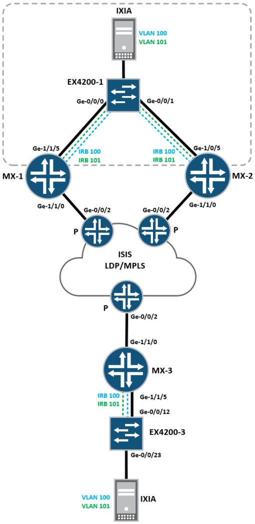
The topology and configuration remains pretty much the same, except that MX-1 and MX-2 each connect back to EX4200-1, for VLAN 100 and VLAN 101, with the same IRB interfaces present on each MX router, essentially a very basic site with 2 PEs for redundancy.
Let’s recap the EVPN configuration on each MX1, I’ve got the exact same configuration loaded on MX-2 and MX-3, the only differences being the interface numbers and a unique RD for each site.
MX-1:
-
tim@MX5-1> show configuration routing-instances
-
EVPN-100 {
-
instance-type virtual-switch;
-
route-distinguisher 1.1.1.1:100;
-
vrf-target target:100:100;
-
protocols {
-
evpn {
-
extended-vlan-list 100-101;
-
default-gateway do-not-advertise;
-
}
-
}
-
bridge-domains {
-
VL-100 {
-
vlan-id 100;
-
interface ge-1/1/5.100;
-
routing-interface irb.100;
-
}
-
VL-101 {
-
vlan-id 101;
-
interface ge-1/1/5.101;
-
routing-interface irb.101;
-
}
-
}
-
}
-
VPN-100 {
-
instance-type vrf;
-
interface irb.100;
-
interface irb.101;
-
route-distinguisher 100.100.100.1:100;
-
vrf-target target:1:100;
-
vrf-table-label;
-
}
-
tim@MX5-1>
Essentially, each site is configured exactly the same, except for a unique RD per site, and differences in the interface numbering.
In terms of providing active/standby redundancy at the main site, for layer-2 and layer-3 simultaneously, we would historically use VPLS combined with VRRP on the IRB interfaces to provide connectivity.
However this isn’t a perfect solution, for the following reasons:
- Unlike EVPN – VPLS needs unique IPv4 GW/MAC addresses at each site, inside the same VPN, so the only way to do active-standby redundancy is with VRRP.
- VRRP designs can become complex, ensuring that everything is tracked and monitored – partial failures can be hard to track and things can get over-complicated.
- Traffic tromboning can occur where VRRP is used
Regarding point 3
Imagine a scenario where each PE is providing a layer-3 default gateway for each VLAN on each PE, where MX1 is active for VLAN 100 and MX2 is active for VLAN 101

It looks simple enough, but traffic tromboning can occur quite easily – due to the reliance on VRRP, for example if host-1 in VLAN 100 wants to send traffic to host-2 in VLAN 101, connected to the same switch – the following things happen:
- The packet hits the VRRP active VLAN 100 IRB interface on MX1
- Because VLAN 101 is in standby mode on MX1 – it can’t be switched locally
- MX1 forwards the packet towards the MPLS network, because there’s a BGP route coming from MX2 (because it’s VRRP active for VLAN 101)
- Rather than being routed locally, the packet has to traverse the MPLS network, in order to route between VLANs:

Things like this are a pain, and can be mitigated by design and awareness from the start – but in my opinion these sorts of scenarios are good examples of why EVPN was invented, because VPLS never properly solved the basic problems that we get in day to day designs, for simple bread and butter problems like routing between VLANs you end up having a nightmare.
So how does EVPN do it differently?
First, lets look at the configuration required to convert the lab topology into EVPN active-standby, it’s pretty simple:
MX-1:
-
tim@MX5-1# run show configuration interfaces ge-1/1/5
-
flexible-vlan-tagging;
-
encapsulation flexible-ethernet-services;
-
esi {
-
00:11:22:33:44:55:66:77:88:99;
-
single-active;
-
}
-
unit 100 {
-
encapsulation vlan-bridge;
-
vlan-id 100;
-
}
-
unit 101 {
-
encapsulation vlan-bridge;
-
vlan-id 101;
-
}
-
[edit]
-
tim@MX5-1#
MX-2:
-
tim@MX5-2# run show configuration interfaces ge-1/0/5
-
flexible-vlan-tagging;
-
encapsulation flexible-ethernet-services;
-
esi {
-
00:11:22:33:44:55:66:77:88:99;
-
single-active;
-
}
-
unit 100 {
-
encapsulation vlan-bridge;
-
vlan-id 100;
-
}
-
unit 101 {
-
encapsulation vlan-bridge;
-
vlan-id 101;
-
}
-
[edit]
-
tim@MX5-2#
In basic EVPN where sites are single-homed, the “ESI” (Ethernet segment identifier) remains at zero, however whenever you have single-active multi-homing or active-active multi-homing, the ESI value must be configured to a non-default value. It’s purpose is to identify an Ethernet segment and as such it identifies the entire “site” or “data-centre” to other PE routers on the network, it’s configured under the physical Ethernet interface and must be the same across the segment, in this case for MX1 and MX2 access-facing interfaces
Secondly, under the ESI configuration the PE interfaces are configured to operate in “single-active” mode, which should be self explanatory to most readers 🙂
How does this alter the EVPN control-plane? lets have a more detailed look at the EVPN instance on MX-1
-
tim@MX5-1> show evpn instance extensive
-
Instance: EVPN-100
-
Route Distinguisher: 1.1.1.1:100
-
Per-instance MAC route label: 299776
-
MAC database status Local Remote
-
Total MAC addresses: 2 2
-
Default gateway MAC addresses: 2 0
-
Number of local interfaces: 2 (2 up)
-
Interface name ESI Mode Status
-
ge-1/1/5.100 00:11:22:33:44:55:66:77:88:99 single-active Up
-
ge-1/1/5.101 00:11:22:33:44:55:66:77:88:99 single-active Up
-
Number of IRB interfaces: 2 (2 up)
-
Interface name VLAN ID Status L3 context
-
irb.100 100 Up VPN-100
-
irb.101 101 Up VPN-100
-
Number of bridge domains: 2
-
VLAN ID Intfs / up Mode MAC sync IM route label
-
100 1 1 Extended Enabled 302080
-
101 1 1 Extended Enabled 301872
-
Number of neighbors: 2
-
10.10.10.2
-
Received routes
-
MAC address advertisement: 0
-
MAC+IP address advertisement: 0
-
Inclusive multicast: 2
-
Ethernet auto-discovery: 1
-
10.10.10.3
-
Received routes
-
MAC address advertisement: 2
-
MAC+IP address advertisement: 2
-
Inclusive multicast: 2
-
Ethernet auto-discovery: 0
-
Number of ethernet segments: 1
-
ESI: 00:11:22:33:44:55:66:77:88:99
-
Status: Resolved by IFL ge-1/1/5.100
-
Local interface: ge-1/1/5.100, Status: Up/Forwarding
-
Number of remote PEs connected: 1
-
Remote PE MAC label Aliasing label Mode
-
10.10.10.2 301008 0 single-active
-
Designated forwarder: 10.10.10.1
-
Backup forwarder: 10.10.10.2
-
Advertised MAC label: 301232
-
Advertised aliasing label: 301232
-
Advertised split horizon label: 0
-
Instance: __default_evpn__
-
Route Distinguisher: 10.10.10.1:0
-
VLAN ID: None
-
Per-instance MAC route label: 299808
-
MAC database status Local Remote
-
Total MAC addresses: 0 0
-
Default gateway MAC addresses: 0 0
-
Number of local interfaces: 0 (0 up)
-
Number of IRB interfaces: 0 (0 up)
-
Number of bridge domains: 0
-
Number of neighbors: 1
-
10.10.10.2
-
Received routes
-
Ethernet auto-discovery: 0
-
Ethernet Segment: 1
-
Number of ethernet segments: 0
-
tim@MX5-1>
A couple of things to note:
- EVPN is running in single-active mode, for ge-1/1/5.100 and ge-1/0/5.101
- The access-interface (ge-1/1/5) on MX1 is shown to be up/forwarding, making this the active PE
- MX1 is operating in single-active mode
- The designated forwarder is MX1 (10.10.10.1)
- The backup designated forwarder is MX2 (10.10.10.2)
Because MX-1 is the active PE, lets take a look at BGP on MX-3 to see what routes are advertised from the redundant site, to a remote site:
(Note – I currently have 2Mbps of IXIA traffic flowing bi-bidirectionally between each site, in each VLAN)
-
EVPN-100.evpn.0: 17 destinations, 17 routes (17 active, 0 holddown, 0 hidden)
-
+ = Active Route, – = Last Active, * = Both
-
1:1.1.1.1:100::112233445566778899::0/304
-
*[BGP/170] 04:17:27, localpref 100, from 10.10.10.1
-
AS path: I, validation-state: unverified
-
> to 192.169.100.15 via ge-1/1/0.0, Push 300912
-
1:10.10.10.1:0::112233445566778899::FFFF:FFFF/304
-
*[BGP/170] 04:17:27, localpref 100, from 10.10.10.1
-
AS path: I, validation-state: unverified
-
> to 192.169.100.15 via ge-1/1/0.0, Push 300912
-
1:10.10.10.2:0::112233445566778899::FFFF:FFFF/304
-
*[BGP/170] 13:50:18, localpref 100, from 10.10.10.2
-
AS path: I, validation-state: unverified
-
> to 192.169.100.15 via ge-1/1/0.0, Push 300848
-
2:1.1.1.1:100::100::00:00:2e:18:6d:e1/304
-
*[BGP/170] 04:17:23, localpref 100, from 10.10.10.1
-
AS path: I, validation-state: unverified
-
> to 192.169.100.15 via ge-1/1/0.0, Push 300912
-
2:1.1.1.1:100::101::00:00:2e:e6:77:95/304
-
*[BGP/170] 04:17:23, localpref 100, from 10.10.10.1
-
AS path: I, validation-state: unverified
-
> to 192.169.100.15 via ge-1/1/0.0, Push 300912
-
2:1.1.1.1:100::100::00:00:2e:18:6d:e1::192.168.100.10/304
-
*[BGP/170] 04:17:23, localpref 100, from 10.10.10.1
-
AS path: I, validation-state: unverified
-
> to 192.169.100.15 via ge-1/1/0.0, Push 300912
-
2:1.1.1.1:100::101::00:00:2e:e6:77:95::192.168.101.10/304
-
*[BGP/170] 04:17:23, localpref 100, from 10.10.10.1
-
AS path: I, validation-state: unverified
-
> to 192.169.100.15 via ge-1/1/0.0, Push 300912
-
3:1.1.1.1:100::100::10.10.10.1/304
-
*[BGP/170] 04:17:26, localpref 100, from 10.10.10.1
-
AS path: I, validation-state: unverified
-
> to 192.169.100.15 via ge-1/1/0.0, Push 300912
-
3:1.1.1.1:100::101::10.10.10.1/304
-
*[BGP/170] 13:50:26, localpref 100, from 10.10.10.1
-
AS path: I, validation-state: unverified
-
> to 192.169.100.15 via ge-1/1/0.0, Push 300912
-
3:1.1.1.2:100::100::10.10.10.2/304
-
*[BGP/170] 13:50:18, localpref 100, from 10.10.10.2
-
AS path: I, validation-state: unverified
-
> to 192.169.100.15 via ge-1/1/0.0, Push 300848
-
3:1.1.1.2:100::101::10.10.10.2/304
-
*[BGP/170] 13:50:18, localpref 100, from 10.10.10.2
-
AS path: I, validation-state: unverified
-
> to 192.169.100.15 via ge-1/1/0.0, Push 300848
-
tim@MX5-3>
We covered type-2 and type-3 routes in the previous labs, but here we have a new type-1 route being received on MX-3, what’s that all about? lets take a deeper look:
-
tim@MX5-3> show route protocol bgp table EVPN-100.evpn.0 extensive
-
EVPN-100.evpn.0: 17 destinations, 17 routes (17 active, 0 holddown, 0 hidden)
-
1:1.1.1.1:100::112233445566778899::0/304 (1 entry, 1 announced)
-
*BGP Preference: 170/-101
-
Route Distinguisher: 1.1.1.1:100
-
Next hop type: Indirect
-
Address: 0x2a7b880
-
Next-hop reference count: 16
-
Source: 10.10.10.1
-
Protocol next hop: 10.10.10.1
-
Indirect next hop: 0x2 no-forward INH Session ID: 0x0
-
State: <Secondary Active Int Ext>
-
Local AS: 100 Peer AS: 100
-
Age: 4:21:25 Metric2: 1
-
Validation State: unverified
-
Task: BGP_100.10.10.10.1+179
-
Announcement bits (1): 0-EVPN-100-evpn
-
AS path: I
-
Communities: target:100:100
-
Import Accepted
-
Route Label: 301232
-
Localpref: 100
-
Router ID: 10.10.10.1
-
Primary Routing Table bgp.evpn.0
-
Indirect next hops: 1
-
Protocol next hop: 10.10.10.1 Metric: 1
-
Indirect next hop: 0x2 no-forward INH Session ID: 0x0
-
Indirect path forwarding next hops: 1
-
Next hop type: Router
-
Next hop: 192.169.100.15 via ge-1/1/0.0
-
Session Id: 0x0
-
10.10.10.1/32 Originating RIB: inet.3
-
Metric: 1 Node path count: 1
-
Forwarding nexthops: 1
-
Nexthop: 192.169.100.15 via ge-1/1/0.0
-
1:10.10.10.1:0::112233445566778899::FFFF:FFFF/304 (1 entry, 1 announced)
-
*BGP Preference: 170/-101
-
Route Distinguisher: 10.10.10.1:0
-
Next hop type: Indirect
-
Address: 0x2a7b880
-
Next-hop reference count: 16
-
Source: 10.10.10.1
-
Protocol next hop: 10.10.10.1
-
Indirect next hop: 0x2 no-forward INH Session ID: 0x0
-
State: <Secondary Active Int Ext>
-
Local AS: 100 Peer AS: 100
-
Age: 4:21:25 Metric2: 1
-
Validation State: unverified
-
Task: BGP_100.10.10.10.1+179
-
Announcement bits (1): 0-EVPN-100-evpn
-
AS path: I
-
Communities: target:100:100 esi-label:single-active (label 0)
-
Import Accepted
-
Localpref: 100
-
Router ID: 10.10.10.1
-
Primary Routing Table bgp.evpn.0
-
Indirect next hops: 1
-
Protocol next hop: 10.10.10.1 Metric: 1
-
Indirect next hop: 0x2 no-forward INH Session ID: 0x0
-
Indirect path forwarding next hops: 1
-
Next hop type: Router
-
Next hop: 192.169.100.15 via ge-1/1/0.0
-
Session Id: 0x0
-
10.10.10.1/32 Originating RIB: inet.3
-
Metric: 1 Node path count: 1
-
Forwarding nexthops: 1
-
Nexthop: 192.169.100.15 via ge-1/1/0.0
-
1:10.10.10.2:0::112233445566778899::FFFF:FFFF/304 (1 entry, 1 announced)
-
*BGP Preference: 170/-101
-
Route Distinguisher: 10.10.10.2:0
-
Next hop type: Indirect
-
Address: 0x2a7ae54
-
Next-hop reference count: 6
-
Source: 10.10.10.2
-
Protocol next hop: 10.10.10.2
-
Indirect next hop: 0x2 no-forward INH Session ID: 0x0
-
State: <Secondary Active Int Ext>
-
Local AS: 100 Peer AS: 100
-
Age: 13:54:16 Metric2: 1
-
Validation State: unverified
-
Task: BGP_100.10.10.10.2+179
-
Announcement bits (1): 0-EVPN-100-evpn
-
AS path: I
-
Communities: target:100:100 esi-label:single-active (label 0)
-
Import Accepted
-
Localpref: 100
-
Router ID: 10.10.10.2
-
Primary Routing Table bgp.evpn.0
-
Indirect next hops: 1
-
Protocol next hop: 10.10.10.2 Metric: 1
-
Indirect next hop: 0x2 no-forward INH Session ID: 0x0
-
Indirect path forwarding next hops: 1
-
Next hop type: Router
-
Next hop: 192.169.100.15 via ge-1/1/0.0
-
Session Id: 0x0
-
10.10.10.2/32 Originating RIB: inet.3
-
Metric: 1 Node path count: 1
-
Forwarding nexthops: 1
-
Nexthop: 192.169.100.15 via ge-1/1/0.0
The Type-1 route is known as an AD or Auto-Discovery route, and it’s broken up into two distinct chunks:
- A per-EVI AD route (line 4
- A per-ESI AD route (lines 71 and 87)
The first route (line 4) is known as a per-EVI route, and contains what’s known as the “aliasing label” technically this isn’t required in an active-standby situation, as it exists to ensure that traffic can be forwarded equally where you have multiple PEs in an active-active setup. It solves the problem of traffic polarisation caused by a CE hashing traffic on one egress link only – resulting in that being replicated in the control-plane, so return traffic is also polarised, the aliasing label gets around this simply because a remote PE treats it like a regular MAC/IP route, but more on that in the next blog 🙂
The other two routes (line 71 and 87) are Per-ESI AD routes, and contain the ESI of the site, advertised from PE1 and PE2, you notice that the community is set as “target:100:100 esi-label:single-active” and has a label-value of 0. This is essentially telling MX3 that the ESI is running in single-active mode, if it was running in active-active mode – then a non-zero MPLS label would be present – in order to cater for split horizon and BUM traffic. In this case the setup is single-active and so there will only ever be one route at a time back to site 1.
These routes also speed up convergence, if you’re advertising 1000s of MAC/IP routes and you get a link failure, rather than a PE having to send BGP messages to withdraw all those routes, it can simply withdraw the Ethernet AD routes – which speeds up convergence.
Next lets take a look at what’s going on at the main site, and see what MX1 is advertising to MX2:
-
tim@MX5-1> show route advertising-protocol bgp 10.10.10.2 evpn-esi-value 00:11:22:33:44:55:66:77:88:99 detail
-
VPN-100.inet.0: 8 destinations, 14 routes (8 active, 0 holddown, 0 hidden)
-
EVPN-100.evpn.0: 16 destinations, 16 routes (16 active, 0 holddown, 0 hidden)
-
* 1:1.1.1.1:100::112233445566778899::0/304 (1 entry, 1 announced)
-
BGP group iBGP-PEs type Internal
-
Route Distinguisher: 1.1.1.1:100
-
Route Label: 301232
-
Nexthop: Self
-
Flags: Nexthop Change
-
Localpref: 100
-
AS path: [100] I
-
Communities: target:100:100
-
__default_evpn__.evpn.0: 3 destinations, 3 routes (3 active, 0 holddown, 0 hidden)
-
* 1:10.10.10.1:0::112233445566778899::FFFF:FFFF/304 (1 entry, 1 announced)
-
BGP group iBGP-PEs type Internal
-
Route Distinguisher: 10.10.10.1:0
-
Nexthop: Self
-
Flags: Nexthop Change
-
Localpref: 100
-
AS path: [100] I
-
Communities: target:100:100 esi-label:single-active (label 0)
-
* 4:10.10.10.1:0::112233445566778899:10.10.10.1/304 (1 entry, 1 announced)
-
BGP group iBGP-PEs type Internal
-
Route Distinguisher: 10.10.10.1:0
-
Nexthop: Self
-
Flags: Nexthop Change
-
Localpref: 100
-
AS path: [100] I
-
Communities: es-import-target:22-33-44-55-66-77
You can see that there’s a new “type-4” route being advertised, this is known as an “Ethernet Segment (ES) route” and is advertised by PE routers which are configured with non-zero ESI values. Essentially, it’s a special extended community (ES-Import-target) that each PE router will import if they both have the same ESI configured, it means that two PE routers remote from one another, know that they’re both connected to the same Ethernet segment, all other PE routers with default, or non-zero ESI values filter these advertisements.
So a quick recap – we’ve looked at the new route types, the control-plane and the configuration, the next step is to see how well it works, first a quick recap of the diagram:

I’ve created a flow of IXIA traffic bi-bidirectionally between the top site and the bottom site, if I go to MX-1 and look at the MPLS facing interface, we should see the traffic:
Physical interface: ge-1/1/0, Enabled, Physical link is Up
Interface index: 147, SNMP ifIndex: 525
Link-level type: Ethernet, MTU: 1514, MRU: 1522, Speed: 1000mbps, BPDU Error: None, MAC-REWRITE Error: None, Loopback: Disabled, Source filtering: Disabled,
Flow control: Enabled, Auto-negotiation: Enabled, Remote fault: Online
Pad to minimum frame size: Disabled
Device flags : Present Running
Interface flags: SNMP-Traps Internal: 0x0
Link flags : None
CoS queues : 8 supported, 8 maximum usable queues
Current address: a8:d0:e5:5b:7c:90, Hardware address: a8:d0:e5:5b:7c:90
Last flapped : 2016-06-10 20:15:19 UTC (5d 19:13 ago)
Input rate : 5599000 bps (500 pps)
Output rate : 5583408 bps (499 pps)
So it’s clear that traffic is being forwarded by MX-1, because I’m sending packets at an exact rate of 1000pps we should be able to measure how quickly fail-over occurs by counting the number of lost packets, for example – at 1000pps, if I lose 50 packets, that yields a fail-over time of 50ms.
First an easy failure – I’ll shut down ge-0/0/0 on EX4200-1, this will put the interface down/down on MX-1 and we’ll measure how long it takes to recover:
imtech@ex4200-1# set interfaces ge-0/0/0 disable
{master:0}[edit]
imtech@ex4200-1# commit
configuration check succeeds
commit complete
{master:0}[edit]
imtech@ex4200-1#
Lets look at much traffic was lost:

Frames delta = 1077, so just a fraction longer than 1 second to failover, which isn’t THAT bad, we might be able to improve it later..
Lets check the EVPN instance to see how things have changed:
on MX1:
-
im@MX5-1> show evpn instance extensive
-
Instance: EVPN-100
-
Route Distinguisher: 1.1.1.1:100
-
Per-instance MAC route label: 299776
-
MAC database status Local Remote
-
Total MAC addresses: 0 3
-
Default gateway MAC addresses: 0 0
-
Number of local interfaces: 2 (0 up)
-
Interface name ESI Mode Status
-
ge-1/1/5.100 00:11:22:33:44:55:66:77:88:99 single-active Down
-
ge-1/1/5.101 00:11:22:33:44:55:66:77:88:99 single-active Down
-
Number of IRB interfaces: 2 (0 up)
-
Interface name VLAN ID Status L3 context
-
irb.100 100 Down VPN-100
-
irb.101 101 Down VPN-100
-
Number of bridge domains: 2
-
VLAN ID Intfs / up Mode MAC sync IM route label
-
100 1 0 Extended Enabled
-
101 1 0 Extended Enabled
-
Number of neighbors: 2
-
10.10.10.2
-
Received routes
-
MAC address advertisement: 1
-
MAC+IP address advertisement: 1
-
Inclusive multicast: 2
-
Ethernet auto-discovery: 2
-
10.10.10.3
-
Received routes
-
MAC address advertisement: 2
-
MAC+IP address advertisement: 2
-
Inclusive multicast: 2
-
Ethernet auto-discovery: 0
-
Number of ethernet segments: 1
-
ESI: 00:11:22:33:44:55:66:77:88:99
-
Status: Resolved by NH 1048582
-
Local interface: ge-1/1/5.100, Status: Down
-
Number of remote PEs connected: 1
-
Remote PE MAC label Aliasing label Mode
-
10.10.10.2 301008 301008 single-active
-
Designated forwarder: 10.10.10.2
-
Advertised MAC label: 301232
-
Advertised aliasing label: 301232
-
Advertised split horizon label: 0
-
Instance: __default_evpn__
-
Route Distinguisher: 10.10.10.1:0
-
VLAN ID: None
-
Per-instance MAC route label: 299808
-
MAC database status Local Remote
-
Total MAC addresses: 0 0
-
Default gateway MAC addresses: 0 0
-
Number of local interfaces: 0 (0 up)
-
Number of IRB interfaces: 0 (0 up)
-
Number of bridge domains: 0
-
Number of neighbors: 1
-
10.10.10.2
-
Received routes
-
Ethernet auto-discovery: 0
-
Ethernet Segment: 1
-
Number of ethernet segments: 0
-
tim@MX5-1>
So it’s pretty clear that things have gone down, and MX2 is the new active PE router, lets check it out:
-
tim@MX5-2> show evpn instance extensive
-
Instance: EVPN-100
-
Route Distinguisher: 1.1.1.2:100
-
Per-instance MAC route label: 299776
-
MAC database status Local Remote
-
Total MAC addresses: 1 2
-
Default gateway MAC addresses: 2 0
-
Number of local interfaces: 2 (2 up)
-
Interface name ESI Mode Status
-
ge-1/0/5.100 00:11:22:33:44:55:66:77:88:99 single-active Up
-
ge-1/0/5.101 00:11:22:33:44:55:66:77:88:99 single-active Up
-
Number of IRB interfaces: 2 (2 up)
-
Interface name VLAN ID Status L3 context
-
irb.100 100 Up VPN-100
-
irb.101 101 Up VPN-100
-
Number of bridge domains: 2
-
VLAN ID Intfs / up Mode MAC sync IM route label
-
100 1 1 Extended Enabled 302272
-
101 1 1 Extended Enabled 302224
-
Number of neighbors: 1
-
10.10.10.3
-
Received routes
-
MAC address advertisement: 2
-
MAC+IP address advertisement: 2
-
Inclusive multicast: 2
-
Ethernet auto-discovery: 0
-
Number of ethernet segments: 1
-
ESI: 00:11:22:33:44:55:66:77:88:99
-
Status: Resolved by IFL ge-1/0/5.100
-
Local interface: ge-1/0/5.100, Status: Up/Forwarding
-
Designated forwarder: 10.10.10.2
-
Advertised MAC label: 301008
-
Advertised aliasing label: 301008
-
Advertised split horizon label: 0
-
Instance: __default_evpn__
-
Route Distinguisher: 10.10.10.2:0
-
VLAN ID: None
-
Per-instance MAC route label: 299808
-
MAC database status Local Remote
-
Total MAC addresses: 0 0
-
Default gateway MAC addresses: 0 0
-
Number of local interfaces: 0 (0 up)
-
Number of IRB interfaces: 0 (0 up)
-
Number of bridge domains: 0
-
Number of neighbors: 0
-
Number of ethernet segments: 0
-
tim@MX5-2>
If we look at the MPLS facing interface on MX2, we should see that all traffic is being sent and received via the MPLS network:
tim@MX5-2> show interfaces ge-1/1/0
Physical interface: ge-1/1/0, Enabled, Physical link is Up
Interface index: 147, SNMP ifIndex: 526
Link-level type: Ethernet, MTU: 1514, MRU: 1522, Speed: 1000mbps, BPDU Error: None, MAC-REWRITE Error: None, Loopback: Disabled, Source filtering: Disabled,
Flow control: Enabled, Auto-negotiation: Enabled, Remote fault: Online
Pad to minimum frame size: Disabled
Device flags : Present Running
Interface flags: SNMP-Traps Internal: 0x0
Link flags : None
CoS queues : 8 supported, 8 maximum usable queues
Current address: a8:d0:e5:5b:75:90, Hardware address: a8:d0:e5:5b:75:90
Last flapped : 2016-06-10 20:08:17 UTC (5d 19:42 ago)
Input rate : 5605824 bps (502 pps)
Output rate : 5584392 bps (501 pps)
The solution itself is a lot more elegant than traditional FHRP (First hop routing protocols) such as VRRP or HSRP.
- Because MX1 and MX2 automatically learn about each other via the MPLS network and the type-4 Ethernet-Segment route, and NOT the LAN (like HSRP) – if there’s any problem with the MPLS side connected to the active router, it transitions to standby and the solution fails over.
If I fail the MPLS interface on the “P” router connected to MX1, we get failover in less than 1 second:
Axians@m10i-1# set interfaces ge-0/0/2 disable
[edit]
Axians@m10i-1# commit
commit complete
Then check the packet loss in IXIA:

The solution recovers from the failure in 912ms.
This is pretty great, not least because it works reliably – but most of this functionality is built directly into the protocol, I haven’t had to do any crazy tracking of routes, I haven’t needed to go anywhere near IP SLA or any of that horror that is a massive pain when designing this sort of thing, with EVPN – things are pretty simple and work reliably.
It’s not perfect however, unlike HSRP or VRRP which form an adjacency over a LAN via Multicast, EVPN doesn’t do this – all information about other PEs is sent and received via BGP. If you have a complex LAN environment and a failure leaves the PEs isolated – you don’t get a traditional split-brain scenario like you would with HSRP or VRRP, the solution simply doesn’t fail at all, the basic triggers for failure are that the physical interface goes down, the MPLS side goes down, or the entire PE goes down.
This can easily be demonstrated by breaking the logical interface on EX4200-1 whilst leaving the physical interface up/up:
imtech@ex4200-1# set interfaces ge-0/0/0.0 disable
{master:0}[edit]
imtech@ex4200-1# commit
configuration check succeeds
commit complete
The whole solution breaks, and stays broken forever:

So you still need to be careful with the design and the different way in which EVPN operates, incidentally you can use things like Ethernet OAM to get around this problem:
Just for laughs, lets apply a basic Ethernet OAM config to MX1, MX2 and the EX4200:
OAM template (shown just on MX-1):
-
oam {
-
ethernet {
-
connectivity-fault-management {
-
action-profile bring-down {
-
event {
-
interface-status-tlv down;
-
adjacency-loss;
-
}
-
action {
-
interface-down;
-
}
-
}
-
maintenance-domain “IEEE level 4” {
-
level 4;
-
maintenance-association PE1 {
-
short-name-format character-string;
-
continuity-check {
-
interval 100ms;
-
interface-status-tlv;
-
}
-
mep 1 {
-
interface ge-1/1/5.100;
-
direction down;
-
auto-discovery;
-
remote-mep 2 {
-
action-profile bring-down;
-
}
-
}
-
}
-
}
-
}
-
}
Just for clarity, the OAM configuration ensures that if there’s a problem with connectivity between MX1 – EX4200-1 and MX2 – EX4200-1 but the physical interfaces remain up/up, OAM will detect the connectivity loss, and automatically tear the line-protocol of the interface to the down/down status, and force EVPN to fail-over,
lets repeat the exact same test again, with the OAM configuration applied to the PEs and the switch:
imtech@ex4200-1# set interfaces ge-0/0/0.0 disable
{master:0}[edit]
imtech@ex4200-1# commit
configuration check succeeds
commit complete
and check the packet-loss with IXIA:
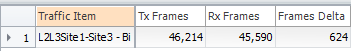
Not bad! 612 packets lost, equals failure and convergence in 624ms, which is a lot better than the original 1077ms when failing the physical interface, and a hell of a lot better than it being down forever, if the network experiences a non-direct failure, (software/logical fail)
Anyway I hope you’ve found this useful, there’s a few bits I’ve skipped over – but I’ll cover those in more detail when I do all-active redundancy in the next blog 🙂

Hello Tim,
Interesting article!
I am wondering do you also have result of measurement in case of a PE node failover?
Interested wot the amount of packet loss will be when for example MX-1 crashes (Node Failover) and MX-2 has to take over.
And wot the recovery times will be when MX-1 recovers and becomes the active PE node again.
Looking forward to hear from you.
LikeLike
I was recently doing a similar lab experiment and found that the last “stays broken forever” scenario was caused by the MAC address changing – clearing the arp/mac tables on the CE would fix it.
OAM is a great idea, another option that worked in the lab setup was to hard-code the same MAC address in the EVPN instance. For example:
MX-1
——-
set routing-instances EVPN-100 protocols evpn interface ge-1/1/5.100 static-mac ee:00:00:00:01:00
set routing-instances EVPN-100 protocols evpn interface ge-1/1/5.100 static-mac ee:00:00:00:01:01
MX-2
——
set routing-instances EVPN-100 protocols evpn interface ge-1/0/5.100 static-mac ee:00:00:00:01:00
set routing-instances EVPN-100 protocols evpn interface ge-1/0/5.100 static-mac ee:00:00:00:01:01
LikeLike