
Quite often on my travels I sometimes encounter technologies I worked on a long time ago that I seem to bump into again later in life, in this case it’s terminating broadband subscribers. Many years ago I worked on large-scale Cisco platform terminating DSL business broadband users on Cisco 7200s over ATM, recently I’ve been involved in a couple of jobs where FTTC users are being terminated on Juniper MX480 routers, using double-tagging and PPPoE, this first post looks into how to setup a Juniper MX router from scratch and terminate PPPoE subscribers authenticated by RADIUS (in this case FreeRadius)
The topology:
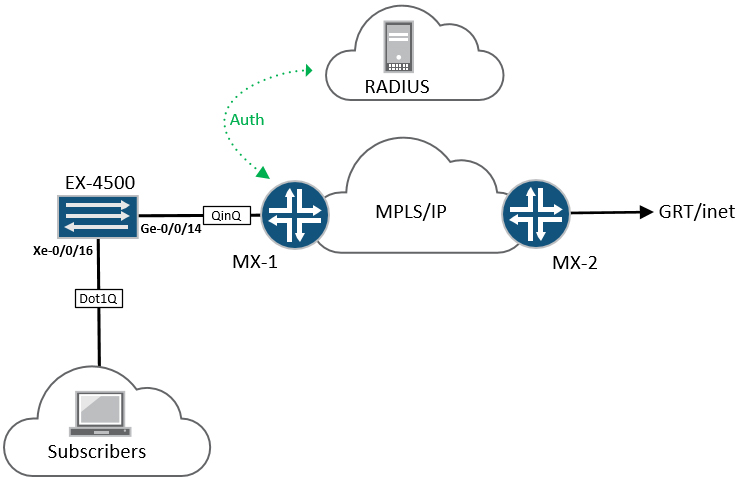
Equipment used for this is as follows:
- MX-1 is a Juniper MX-5 router, acting as the BRAS or BNG
- MX-2 is also an MX-5 is a generic PE with simulated external connectivity
- EX-4500 is self explanatory, and is basically doing QinQ towards the BNG
- RADIUS is an Ubuntu server running FreeRadius (explained in more detail later)
- For Broadband subscribers, I’m lucky to have access to an IXIA XG12 tester
Before we get to the BNG side of things, lets take a look at the access network (EX-4500) essentially, this switch is doing several things:
- Each individual subscriber is assigned their own VLAN, can be imposed on the port, or the subscriber CPE can send tagged-frames,
- The EX-4500 pushes an “S-VLAN” onto all subscriber traffic, so frames heading towards the BNG are double-tagged, or “QinQ’d”
- Outer VLAN or S-TAG = to mark frames coming from the EX-4500
- Inner VLAN or C-TAG = to mark frames coming from each subscriber
- This approach allows for a high degree of scale, as you can encapsulate 4096 C-TAGs inside 4096 S-TAGs (basically you can have 16777216 customers in theory)
If we take a look at the VLAN and interface configuration of the EX-4500, it’s relatively straightforward:
VLAN10 {
vlan-id 10;
dot1q-tunneling {
customer-vlans 100-4000;
}
}
ge-0/0/14 {
unit 0 {
family ethernet-switching {
port-mode trunk;
vlan {
members all;
}
}
}
}
xe-0/0/16 {   # link to PPPoE subs
unit 0 {
family ethernet-switching {
port-mode access;
vlan {
members VLAN10;
    }
This snippet of configuration does a couple of basic things:
- Any frames arriving on xe-0/0/16 with C-VLAN tags within the range of 100-4000 has an additional S-VLAN tag of 10, pushed onto it
- Double-tagged frames can then egress via ge-0/0/14 towards MX-1
- ge-0/0/14 must be configured to trunk “all” vlans,
- Although xe-0/0/16 is configured as an access port in VLAN 10, because that VLAN is configured for dot1q-tunneling, it’s actually expecting single-tagged frames:
tim@EX4500-1; show vlans VLAN10 extensive
VLAN: VLAN10, Created at: Sun Dec 27 05:15:19 2015
802.1Q Tag: 10, Internal index: 30, Admin State: Enabled, Origin: Static
Dot1q Tunneling status: Enabled
Customer VLAN ranges:
 100-4000
Protocol: Port Mode, Mac aging time: 300 seconds
Number of interfaces: Tagged 1 (Active = 0), Untagged 1 (Active = 1)
 ge-0/0/14.0, tagged, trunk
 xe-0/0/16.0*, untagged, access

{master:0}
tim@EX4500-1;
Essentially, that’s all we really need to do, to enable basic QinQ switching, if this was an actual FTTx deployment the switch would really be acting as an MSAN (Multi-service access node) but the principle would be exactly the same – each subscriber has their own VLAN, all of those subscribers are represented by a single VLAN (in this case VLAN 10)
Before we configure the MX as a BNG, lets have a quick recap on what PPPoE is and how it works.
A PPPoE device sat on a layer-2 Ethernet network has the same problem that any normal host has, however a normal host will generally have the luxury of having it’s own IP address configured, or assigned via DHCP through mechanisms most people are familiar with, when a PPPoE host appears on the wire a mechanism known as PPPoED (PPPoE discovery) takes place, which includes the following elements:
PADI (PPPoE active discovery initiation)
When a PPPoE host first appears on the wire, it needs a way of discovering the PPPoE BNG or BRAS server, this is achieved rather simply – the host sends a PADI Ethernet broadcast (ff:ff:ff:ff:ff:ff) containing it’s own source unicast MAC address, a Wireshark capture of it looks like so:
Ethernet II, Src: 00:14:01:00:00:01 (00:14:01:00:00:01), Dst: ff:ff:ff:ff:ff:ff (ff:ff:ff:ff:ff:ff)
 Destination: ff:ff:ff:ff:ff:ff (ff:ff:ff:ff:ff:ff)
 Address: ff:ff:ff:ff:ff:ff (ff:ff:ff:ff:ff:ff)
 .... ..1. .... .... .... .... = LG bit: Locally administered address (this is NOT the factory default)
 .... ...1 .... .... .... .... = IG bit: Group address (multicast/broadcast)
 Source: 00:14:01:00:00:01 (00:14:01:00:00:01)
 Address: 00:14:01:00:00:01 (00:14:01:00:00:01)
 .... ..0. .... .... .... .... = LG bit: Globally unique address (factory default)
 .... ...0 .... .... .... .... = IG bit: Individual address (unicast)
 Type: 802.1Q Virtual LAN (0x8100)
802.1Q Virtual LAN
 000. .... .... .... = Priority: 0
 ...0 .... .... .... = CFI: 0
 .... 0000 0110 0100 = ID: 100
 Type: PPPoE Discovery (0x8863)
PPP-over-Ethernet Discovery
 Version: 1
 Type: 1
 Code: Active Discovery Initiation (PADI)
 Session ID: 0000
 Payload Length: 4
PPPoE Tags
 Tag: Service-Name
- Lines 2 – 3 show the frame as an Ethernet broadcast
- Lines 11 – 14 show the 802.1Q header, set with a single C-VLAN of 100
- Lines 19 – 21 detail the PADI discovery packet
- Line 23 details the PPPoE tags, which might contain an ISP name or QoS variables,
Seeing as this is an Ethernet broadcast, the BNG node should receive it when it does, the mechanism progresses to the next section:
PADO (PPPoE active discovery offer)
Once the BNG node receives the PADI frame, it responds with a PADO (offer) message, this message basically tells the client that there’s an available server on the network, the BNG server name (MX-1) and crucially, the MAC-address of the BNG terminating interface.
Ethernet II, Src: a8:d0:e5:5b:75:78 (a8:d0:e5:5b:75:78), Dst: 00:14:01:00:00:01 (00:14:01:00:00:01)
Destination: 00:14:01:00:00:01 (00:14:01:00:00:01)
Source: a8:d0:e5:5b:75:78 (a8:d0:e5:5b:75:78)
Type: 802.1Q Virtual LAN (0x8100)
802.1Q Virtual LAN
110. .... .... .... = Priority: 6
...0 .... .... .... = CFI: 0
.... 0000 0110 0100 = ID: 100
Type: PPPoE Discovery (0x8863)
PPP-over-Ethernet Discovery
Version: 1
Type: 1
Code: Active Discovery Offer (PADO)
Session ID: 0000
Payload Length: 33
PPPoE Tags
Tag: AC-Name
String Data: MX5-1
Tag: Service-Name
Tag: AC-Cookie
Binary Data: (16 bytes)
- Line 3 contains the BNG’s MAC-address
- Line 13 denotes the frame as a PADO offer
- Line 18 displays the AC-Name – MX-1
It’s also worth noting that multiple BNG’s can be present on the same Ethernet segment, if more than one BNG is present – the client will basically pick one of them, essentially whichever one replies first.
Once the PPPoE client receives the PADO offer frame, it immediately responds with a request known as a PADR:
PADR (PPPoE active discovery request)
The function of the PADR is for the PPPoE client, to say to the BNG “Yep, I’d like to connect, please get me online and give me a session ID” because in all the steps up to this point, the session-ID has been 0x000, a PADR packet looks like so:
Frame 94: 64 bytes on wire (512 bits), 64 bytes captured (512 bits) on interface 0
Ethernet II, Src: 00:14:01:00:00:01 (00:14:01:00:00:01), Dst: a8:d0:e5:5b:75:78 (a8:d0:e5:5b:75:78)
Destination: a8:d0:e5:5b:75:78 (a8:d0:e5:5b:75:78)
Source: 00:14:01:00:00:01 (00:14:01:00:00:01)
Type: 802.1Q Virtual LAN (0x8100)
802.1Q Virtual LAN
000. .... .... .... = Priority: 0
...0 .... .... .... = CFI: 0
.... 0000 0110 0100 = ID: 100
Type: PPPoE Discovery (0x8863)
PPP-over-Ethernet Discovery
Version: 1
Type: 1
Code: Active Discovery Request (PADR)
Session ID: 0000
Payload Length: 24
PPPoE Tags
Tag: Service-Name
Tag: AC-Cookie
Binary Data: (16 bytes)
PADS (PPPoE active discovery session-confirmation)
The last part of the PPPoE discovery sequence is when the BNG sends a PADS packet towards the PPPoE client, this contains a unique session-ID and the service-name, in this case MX5-1, with a session-id of 0x0001
Ethernet II, Src: a8:d0:e5:5b:75:78 (a8:d0:e5:5b:75:78), Dst: 00:14:01:00:00:01 (00:14:01:00:00:01)
Destination: 00:14:01:00:00:01 (00:14:01:00:00:01)
Source: a8:d0:e5:5b:75:78 (a8:d0:e5:5b:75:78)
Type: 802.1Q Virtual LAN (0x8100)
802.1Q Virtual LAN
110. .... .... .... = Priority: 6
...0 .... .... .... = CFI: 0
.... 0000 0110 0100 = ID: 100
Type: PPPoE Discovery (0x8863)
PPP-over-Ethernet Discovery
Version: 1
Type: 1
Code: Active Discovery Session-confirmation (PADS)
Session ID: 0001
Payload Length: 33
PPPoE Tags
Tag: Service-Name
Tag: AC-Name
String Data: MX5-1
Tag: AC-Cookie
Binary Data: (16 bytes)
It’s also worth noting that multiple BNG’s can be present on the same Ethernet segment, if more than one BNG is present – the client will basically pick one of them, essentially whichever one replies first.
Once the client receives the PADS session-confirmation, the PPPoE discovery mechanism is complete, next comes PPP LCP and NCP, in order to authenticate the host with RADIUS and provide it with things such as an IP address, LDP and NCP are skipped here for brevity, but will be covered a little later when we move onto the MX configuration.
Juniper MX-5 BNG configuration
Before we get started on the BNG configuration, MX’s require licensing to enable the subscriber management features, the routers I’m using are all licensed, but you can enables these features for a 30 day trial. In terms of hardware I’m using an MX-5 with a 20x1GE PIC shown in line 14 below
tim@MX5-1 show chassis hardware
Hardware inventory:
Item Version Part number Serial number Description
Chassis G0081 MX5-T
Midplane REV 08 711-038215 CAAM9197 MX5-T
PEM 0 Rev 04 740-028288 WA02242 AC Power Entry Module
Routing Engine BUILTIN BUILTIN Routing Engine
TFEB 0 BUILTIN BUILTIN Forwarding Engine Processor
QXM 0 REV 06 711-028408 CAAM9539 MPC QXM
FPC 0 BUILTIN BUILTIN MPC BUILTIN
MIC 0 BUILTIN BUILTIN 4x 10GE XFP
PIC 0 BUILTIN BUILTIN 4x 10GE XFP
FPC 1 BUILTIN BUILTIN MPC BUILTIN
MIC 0 REV 24 750-028392 ZF6501 3D 20x 1GE(LAN) SFP
PIC 0 BUILTIN BUILTIN 10x 1GE(LAN) SFP
Xcvr 0 p NON-JNPR FNS1005Q7VW SFP-SX
PIC 1 BUILTIN BUILTIN 10x 1GE(LAN) SFP
Xcvr 0 NON-JNPR ZZ201280393 SFP-SX
Xcvr 9 NON-JNPR AABM362 UNSUPPORTED
Fan Tray Fan Tray
Traceoptions
The first step in doing BNG on Juniper MX is to enable plenty of traceoptions, there are a lot of individual pieces to the puzzle which must all fit perfectly, if you find yourself in a position where certain things don’t work – you’re going to need to know which traceoptions to use and where to apply them, for this example I’ll globally define an apply-group containing everything I need:
groups {
BNG-TRACES {
system {
auto-configuration {
traceoptions {
file autoconf.log size 10m files 10;
level verbose;
flag all;
}
}
processes {
general-authentication-service {
traceoptions {
file authlog.log size 10m files 10;
flag radius;
}
}
dhcp-service {
traceoptions {
file dhcp.log size 10m files 10;
}
}
}
}
protocols {
ppp-service {
traceoptions {
file pppserv.log size 10m files 10;
level all;
flag all;
}
}
ppp {
traceoptions {
file ppp.log size 10m files 10;
level all;
flag all;
}
}
}
}
}
apply-groups BNG-TRACES;
It must be pointed out that with BNG, if a large number of clients try to connect to the device it imposes a heavy load on the routing-engine, so you should only really have the Traceoptions on in an initial setup, or if you’re fault finding – leaving them on can drastically increase the time it takes to get subscribers terminated and connected, turning them all on or off with an apply-group is the easiest way to do this.
Dynamic profiles
Dynamic profiles form the core of the configuration for doing BNG on an MX, this is basically where the magic happens. A dynamic profile is a way of using pre-defined variables which will trigger the router to do certain things automatically when it receives packets on an interface with a dynamic-profile applied. For example in most switched networks you generally need to configure sub-interfaces in order to process traffic coming from different VLANs, you then also need to create layer-3 interfaces to route that very same traffic, all of this takes time and effort. In the broadband world you might have 64000 subscribers logging in and out constantly, so doing this manually would be impossible, by using a dynamic profile – the router can detect packets and automatically create and tear-down interfaces based on certain variables, for example if the packets are tagged with certain VLAN tags, or if it detects DHCP requests, the router can create the interfaces for you, rather than you having to do them statically.
Because in this example we’re terminating subscribers using stacked-VLAN tagging, or “QinQ” we need the router to create two kinds of interfaces, the first is the layer-2 VLAN interface, or Demux interface, the second will be the layer-3 interface that effectively does the routing for the subscriber:
VLAN Demux
dynamic-profiles {
 vlan-prof-0 {
 interfaces {
 demux0 {
 unit $junos-interface-unit; {
 no-traps;
 proxy-arp;
 vlan-tags outer $junos-stacked-vlan-id inner $junos-vlan-id;
 demux-options {
 underlying-interface $junos-interface-ifd-name;
 }
 family pppoe {
 duplicate-protection;
 dynamic-profile pppoe-client-profile;
 }
 }
 }
 }
 }
The snippet above contains some predefined-variables, these are identified by anything starting with “$junos-” it’s basically a template configuration, where the blanks are completed by whatever is inside specific bits of the subscriber traffic, for example:
- Line 5 specifies the junos-interface-unit, this is essentially the interface unit number that the router will generate when the interface is created, instead of you entering it manually
- Line 8 specifies the C-VLAN and S-VLAN tags that the interface should switch packets for, when it’s created, for example if layer-2 frames tagged with S-VLAN 10 and C-VLAN 100 hit the router’s main physical interface, the logical unit associated with VLANs 10/100 will always process those frames.
- Line 10 represents the underlying physical interface for where the packet was received, for example ge-1/0/0
- Line 12 represents the protocol family configured on the underlying interface, in this case it’s PPPoE and it’s referencing the PPPoE client profile for the next section
- Line 13 duplicate-protection basically prevents multiple interfaces from being created is the same user with the same MAC-address keeps trying to login
PPPoE Client profile
The next part of the configuration is to create a client-profile, in which we specify the various options we want to apply to the client, when it initiates it’s connection to the BNG, like the example above it contains a number of variables
pppoe-client-profile {
 routing-instances {
 $junos-routing-instance; {
 interface $junos-interface-name;
 routing-options {
 access {
 route $junos-framed-route-ip-address-prefix {
 next-hop $junos-framed-route-nexthop;
 metric $junos-framed-route-cost;
 preference $junos-framed-route-distance&;
 }
 }
 access-internal {
 route $junos-subscriber-ip-address {
 qualified-next-hop $junos-interface-name;
 }
 }
 }
 }
 }
- Lines 2 – 3 are relatively self explanatory, but it gives an insight into how scalable such a solution can be, the “$junos-routing-instance” is defined by the Radius configuration, so you can quite easily put subscribers into different routing-instances or just the global routing table.
- Lines 7 -10 apply default variables for generating a static host-route for the subscribers connection, “$junos-framed-route-nexthop” is simply itself and points to 0.0.0.0 unless specified by Radius
- Lines 13 – 15 allows the “$junos-framed-route-nexthop” to be resolved by the CPE IP address and logical interface, as a qualified next-hop by the “$junos-interface-name$
The PPPoE logical interface
As mentioned earlier when a PPPoE subscriber is terminated on the BNG, the router creates a dynamic PPPoE interface, this is essentially the layer-3 routed interface for the subscriber. Variables are defined under the pp0 interface stanza and follow a similar regime to the previous sections, things like the address-families and PPP options are defined here.
interfaces {
 interface-set $junos-svlan-interface-set-name; {
 interface pp0 {
 unit $junos-interface-unit;
 }
 }
 pp0 {
 unit $junos-interface-unit; {
 no-traps;
 ppp-options {
 chap;
 pap;
 }
 pppoe-options {
 underlying-interface $junos-underlying-interface;
 server;
 }
 keepalives interval 30;
 family inet {
 rpf-check;
 unnumbered-address $junos-loopback-interface;
 }
 family inet6 {
 address $junos-ipv6-address;
 unnumbered-address $junos-loopback-interface;
 }
 }
 }
 }
 }
}
- Lines 1 – 4 instruct the router to generate a pp0 interface-set based off the SVLAN (outer VLAN tag of the subscriber’s session)
- Lines 7 – 25 give the various options for PPP options, such as PAP/CHAP authentication, the underlying interface which itself becomes a PPPoE server, followed by inet and inet6 address-families
- The address-families themselves are configured for unnumbered IP addressing, in this case the loopback interfaces specified under the routing-instance.
The physical access-facing interface
Before we get to the physical interface, we need to apply the access-profile to the router (aaa-profile) which contains the Radius settings (in the next section) the below configuration binds everything we did in the above 3 sections directly to a physical interface, in this case ge-1/0/0
access-profile aaa-profile;
interfaces {
 ge-1/0/0 {
 flexible-vlan-tagging;
 auto-configure {
 stacked-vlan-ranges {
 dynamic-profile vlan-prof-0 {
 accept [ inet pppoe ];
 ranges {
 10-100,100-4000;
 }
 }
 }
 remove-when-no-subscribers;
 }
 mtu 1530;
 hold-time up 10000 down 10000;
 }
- Line 4 specifies flexible-vlan-tagging, which enables double-tagged QinQ transmission on logical interfaces
- Line 5 is an important one – this instructs the router to auto-configure dynamic interfaces based on all the things we specified so far
- Line 7 applies the VLAN Demux dynamic profile to the physical interface, so that the layer-2 elements will be built correctly
- Lines 9 – 10 specify the VLAN-Ranges for S and C VLAN tags entering the interface, in this case the interface will accept frames within VLAN 10-100 for S Vlans, and 100-4000 for C Vlans.
- Line 14 basically tells the router to delete the logical interface when no subscribers are logged in
Radius and access settings
The settings in the below section are relatively self-explanatory, in this lab the Radius server is connected via the FXP0 interface on the router, and you can see the Radius settings, secret and IP addressing
access {
 radius-server {
 192.168.3.158 {
 port 1812;
 accounting-port 1813;
 secret $9$6vga9CucyKM87n/clMWdV; ## SECRET-DATA
 timeout 10;
 retry 10;
 source-address 192.168.3.61;
 }
 }
 profile lab3 {
 authentication-order radius;
 radius {
 authentication-server 192.168.3.158;
 }
 }
 profile aaa-profile {
 authentication-order radius;
 radius {
 authentication-server 192.168.3.158;
 accounting-server 192.168.3.158;
 options {
 interface-description-format {
 exclude-sub-interface;
 }
 nas-identifier mx5-1;
 accounting-session-id-format decimal;
 vlan-nas-port-stacked-format;
 }
 }
 radius-server {
 192.168.3.158 {
 port 1812;
 accounting-port 1813;
 secret $9$u9AAOBEvWxNdsp0vLN-g4; ## SECRET-DATA
 timeout 10;
 retry 10;
 source-address 192.168.3.61;
 }
 }
 accounting {
 order radius;
 accounting-stop-on-failure;
 accounting-stop-on-access-deny;
 immediate-update;
 coa-immediate-update;
 update-interval 60;
 statistics volume-time;
 }
Routing-instances and address assignment
For this lab we’re going to terminate subscribers directly into a routing-instance, as specified by the Radius server under the user profile, the routing-instance does a number of things, first we define standard routing-instance attributes – such as the fact that it’s a VRF instance, the interfaces and standard L3VPN settings such as the route-distinguisher and the route-target, but we also specify some access properties and address assignment settings:
routing-instances {
 residential {
 instance-type vrf;
 access {
 address-assignment {
 high-utilization 90;
 abated-utilization 70;
 pool TG-POOL {
 family inet {
 network 10.170.0.0/15;
 range range0 {
 low 10.170.0.0;
 high 10.171.255.255;
 }
 }
 }
 }
 }
 interface lo0.100;
 route-distinguisher 100:101;
 vrf-target target:100:101;
 vrf-table-label;
}
- Lines 4 – 13 define the IP address pool directly on the router, and specifies a /15 range, when the subscriber authenticates with Radius, it’ll get allocated a single /32 host address from that range
- Line 19 is required in order for the VRF to function, the address under lo0.100 can effectively be anything, but you cannot commit the configuration with having an interface inside the routing-instance
That’s the subscriber configuration complete! engineers familiar with the Cisco syntax will note that there’s a lot more configuration required to get a Juniper MX router to work, the Cisco PPPoE server settings were very basic and the majority of the configuration is hidden, Juniper BRAS functionality on MX is relatively new compared to Cisco’s which as been around for decades, so there’s a chance it might be simplified in future.
Freeradius
For the lab we’re using a fresh install of Freeradius, the setup of which can be found here: http://freeradius.org/doc/ it’s running on an Ubuntu VM with 1 vCPU and 4GB of RAM. Subscribers are maintained inside a “users” file on the Freeradius server, many attributes are supported by Radius and it’s a very versatile platform – for this example we’re just going to use basic settings:
user1@users.com Cleartext-Password := password1;
 ERX-virtual-Router-Name := residential,
 ERX-Address-Pool-Name := TG-POOL,
 Framed-IP-Netmask = 255.255.255.255,
The above snippet from the users file is pretty simple and self explanatory, Freeradius is actually a very flexible platform with many different configuration options and various different front-ends and GUIs.
- Line 1 means the PPPoE client will fire a CHAP authentication request from user1@users.com with a password of “password1”
- Lines 2 and 3 are interesting, in the sense that they are denoted by ERX values, the ERX was actually an old BRAS platform that Juniper bought in 2002, before it had any real BRAS product of it’s own, and was formally known as “Redstone communications” they specialised in BRAS and they competed primarily with Cisco GSR10k and the old 7500 series, essentially – Juniper has left the old style ERX attributes in place and not renamed them.
- Line 2 essentially tells the BNG to put the subscriber into the “residential” routing-instance, removing this will place the subscriber into the global routing table
- Line 4 basically tells the BNG to allocate a /32 host route from the pool
Connectivity!
A quick re-cap of the diagram:

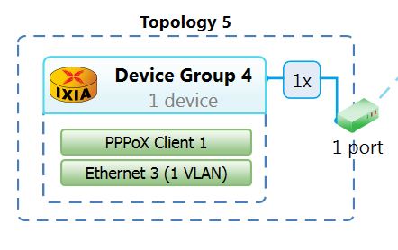
After all that we’re ready to start some connections and see what happens, as I mentioned ages ago – I’ll be using IXIA to simulate PPPoE clients, each client is configured with the username and password specified in the above Freeradius section, I’ll begin by starting a single connection on IXIA:
The connection is successful – lets look at a Wireshark trace of the PPPoE and PPP negotiation:
93 144.144488380 a8:d0:e5:5b:75:78 00:14:01:00:00:01 PPPoED 64 Active Discovery Offer (PADO)
94 144.144715040 00:14:01:00:00:01 a8:d0:e5:5b:75:78 PPPoED 64 Active Discovery Request (PADR)
95 144.220336780 a8:d0:e5:5b:75:78 00:14:01:00:00:01 PPPoED 64 Active Discovery Session-confirmation (PADS)
96 144.221360740 00:14:01:00:00:01 a8:d0:e5:5b:75:78 PPP LCP 64 Configuration Request
97 144.221955780 a8:d0:e5:5b:75:78 00:14:01:00:00:01 PPP LCP 64 Configuration Request
98 144.222081460 00:14:01:00:00:01 a8:d0:e5:5b:75:78 PPP LCP 64 Configuration Ack
99 144.222448200 a8:d0:e5:5b:75:78 00:14:01:00:00:01 PPP LCP 64 Configuration Ack
100 144.223760200 a8:d0:e5:5b:75:78 00:14:01:00:00:01 PPP CHAP 70 Challenge
101 144.223884140 00:14:01:00:00:01 a8:d0:e5:5b:75:78 PPP CHAP 68 Response
102 144.230453160 a8:d0:e5:5b:75:78 00:14:01:00:00:01 PPP CHAP 64 Success
103 144.230675300 00:14:01:00:00:01 a8:d0:e5:5b:75:78 PPP IPCP 64 Configuration Request
104 144.231844920 a8:d0:e5:5b:75:78 00:14:01:00:00:01 PPP IPCP 64 Configuration Nak
Once the PPPoE session is established, LCP negotiates the link parameters, followed by the CHAP authentication, followed by IPCP IP address negotiation (all standard old-school PPP stuff)
Lets take a look on the MX:
tim@MX5-1 show subscribers summary
Subscribers by State
 Active: 2
 Total: 2

Subscribers by Client Type
 VLAN: 1
 PPPoE: 1
 Total: 2

tim@MX5-1 show subscribers extensive
Type: VLAN
Logical System: default
Routing Instance: default
Interface: demux0.1073776124
Interface type: Dynamic
Underlying Interface: ge-1/0/0
Dynamic Profile Name: vlan-prof-0
State: Active
Session ID: 34301
Stacked VLAN Id: 0x8100.10
VLAN Id: 0x8100.100
Login Time: 2016-03-11 23:13:24 UTC

Type: PPPoE
User Name: user1@users.com
IP Address: 10.170.55.177
IP Netmask: 255.255.255.255
Logical System: default
Routing Instance: residential
Interface: pp0.1073776125
Interface type: Dynamic
Interface Set: ge-1/0/0-10
Underlying Interface: demux0.1073776124
Dynamic Profile Name: pppoe-client-profile
MAC Address: 00:14:01:00:00:01
State: Active
Radius Accounting ID: 34302
Session ID: 34302
Stacked VLAN Id: 10
VLAN Id: 100
Login Time: 2016-03-11 23:13:35 UTC
IP Address Pool: TG-POOL

tim@MX5-1;
The astute reader will notice that 2 interfaces are generated, if you remember from the earlier sections – the MX creates two interfaces, a Vlan demux interface for demultiplexing the layer-2 QinQ traffic, and a layer-3 PPPoE interface for routing the subscriber traffic, these interfaces appear on the router along with the others, and can also be viewed by using the standard “show subscribers” command:
tim@MX5-1 show subscribers
Interface IP Address/VLAN ID User Name LS:RI
demux0.1073776124 0x8100.10 0x8100.100 default:default
pp0.1073776125 10.170.55.177 user1@users.com default:residential

tim@MX5-1
From here you can see the VLAN demux0 interface “demux0.1073776124” and it’s associated Ether-type and VLAN tags, 0x8100.10 and 0x8100.100 . Directly below sits the PPPoE interface – pp0.1073776125 and the subscriber has been given an IP address of 10.170.55.177, and the interface has been placed into the default logical-system inside the residential routing-instance, we can see the connected routes by looking in the residential routing-table:
tim@MX5-1 show route table residential.inet.0

residential.inet.0: 3 destinations, 4 routes (3 active, 0 holddown, 0 hidden)
+ = Active Route, - = Last Active, * = Both

10.100.0.2/32 *[Direct/0] 2d 10:41:50
 via lo0.100
10.170.55.177/32 *[Access-internal/12] 00:23:32
 via pp0.1073776125

tim@MX5-1
The routing-instance is configured to directly export the /32 host route to the residential L3 VPN, so if I hop across to MX-2 on the other side of the network, I should see a host route for 10.170.55.177/32 in the VPNv4 BGP table
tim@MX5-2 show route table VRF1.inet.0 10.170.55.177/32

VRF1.inet.0: 4 destinations, 6 routes (4 active, 0 holddown, 0 hidden)
+ = Active Route, - = Last Active, * = Both

10.170.55.177/32 *[BGP/170] 00:34:06, localpref 100, from 1.1.1.253
AS path: I, validation-state: unverified
to 192.169.100.15 via ae0.0, Push 16, Push 300112(top)
[BGP/170] 00:34:06, localpref 100, from 1.1.1.254
AS path: I, validation-state: unverified
to 192.169.100.15 via ae0.0, Push 16, Push 300112(top)

tim@MX5-2
I could also ping, but things get a bit weird when trying to Ping IXIA, so I’ll just send real IXIA traffic from the PPPoE subscriber, to another endpoint behind MX-2:
450Mbps both ways:

If we take a look at the pp0 interface, it shows us the statistics for the traffic and the single logical interface attached to it:
tim@MX5-1 show interfaces pp0 extensive
Physical interface: pp0, Enabled, Physical link is Up
Interface index: 131, SNMP ifIndex: 504, Generation: 134
Type: PPPoE, Link-level type: PPPoE, MTU: 1532, Speed: Unspecified
Device flags : Present Running
Interface flags: Point-To-Point SNMP-Traps
Link type : Full-Duplex
Link flags : None
Physical info : Unspecified
Hold-times : Up 0 ms, Down 0 ms
Current address: Unspecified, Hardware address: Unspecified
Alternate link address: Unspecified

Logical interface pp0.1073776125 (Index 336) (SNMP ifIndex 675) (Generation 34445)
Flags: Up Point-To-Point 0x0 Encapsulation: PPPoE
Interface set: ge-1/0/0-10
PPPoE:
State: SessionUp, Session ID: 1,
Session AC name: MX5-1, Remote MAC address: 00:14:01:00:00:01,
Underlying interface: demux0.1073776124 (Index 335)
Traffic statistics:
Input bytes : 28681394289
Output bytes : 29220920079
Input packets: 20057255
Output packets: 20264510
Local statistics:
Input bytes : 107
Output bytes : 287
Input packets: 6
Output packets: 7
Transit statistics:
Input bytes : 28681394182 440755448 bps
Output bytes : 29220919792 444454096 bps
Input packets: 20057249 38527 pps
Output packets: 20264503 38527 pps
Keepalive settings: Interval 30 seconds, Up-count 1, Down-count 3
LCP state: Opened
NCP state: inet: Opened, inet6: Not-configured, iso: Not-configured, mpls: Not-configured
CHAP state: Success
PAP state: Closed
Protocol inet, MTU: 1492, Generation: 34339, Route table: 6
Flags: Sendbcast-pkt-to-re, uRPF
RPF Failures: Packets: 0, Bytes: 0
Addresses, Flags: Is-Primary
Destination: Unspecified, Local: 10.100.0.2, Broadcast: Unspecified, Generation: 14403

tim@MX5-1
And likewise the Demux0 interface:
tim@MX5-1 show interfaces demux0 extensive
Physical interface: demux0, Enabled, Physical link is Up
Interface index: 128, SNMP ifIndex: 501, Generation: 131
Type: Software-Pseudo, Link-level type: Unspecified, MTU: 9192, Clocking: 1, Speed: Unspecified
Device flags : Present Running
Interface flags: Point-To-Point SNMP-Traps
Link type : Full-Duplex
Link flags : None
Physical info : Unspecified
Hold-times : Up 0 ms, Down 0 ms
Current address: Unspecified, Hardware address: Unspecified
Alternate link address: Unspecified
Last flapped : Never
Statistics last cleared: Never
Traffic statistics:
Input bytes : 0
Output bytes : 0
Input packets: 0
Output packets: 0
IPv6 transit statistics:
Input bytes : 0
Output bytes : 0
Input packets: 0
Output packets: 0
Input errors:
Errors: 0, Drops: 0, Framing errors: 0, Runts: 0, Giants: 0, Policed discards: 0, Resource errors: 0
Output errors:
Carrier transitions: 0, Errors: 0, Drops: 0, MTU errors: 0, Resource errors: 0

Logical interface demux0.1073776124 (Index 335) (SNMP ifIndex 665) (Generation 34444)
Flags: Up 0x0 VLAN-Tag [ 0x8100.10 0x8100.100 ] Encapsulation: ENET2
Demux:
Underlying interface: ge-1/0/0 (Index 140)
Traffic statistics:
Input bytes : 36620166019
Output bytes : 37174746186
Input packets: 25573105
Output packets: 25780359
Local statistics:
Input bytes : 84
Output bytes : 117
Input packets: 2
Output packets: 1
Transit statistics:
Input bytes : 36620165935 441367016 bps
Output bytes : 37174746069 444449192 bps
Input packets: 25573103 38527 pps
Output packets: 25780358 38527 pps
Protocol pppoe
Dynamic Profile: pppoe-client-profile,
Service Name Table: None,
Max Sessions: 32000, Max Sessions VSA Ignore: Off,
Duplicate Protection: On, Short Cycle Protection: Off,
Direct Connect: Off,
AC Name: MX5-1
Generation: 34338, Route table: 0

tim@MX5-1
And that about wraps it up, with an authenticated subscriber and successful end to end traffic there’s not that much more to a basic configuration, in recent times there has been some more exotic ways of terminating subscribers, which I may demonstrate in a later post – specifically Pseudowire headend termination – where the PPPoE sessions are tunnelled directly to a centrally located BNG using L2VPN pseudowires – this makes for a very scalable broadband model.
I hope you found this useful!

Very good job!!!
LikeLike
Hi TIm, I really really need your help. Recently, as part of a new project, we got a Juniper MX104 and one EX4300 switch. We want to configure it for dynamic subscriber management, exactly as you’ve described it here but I couldn’t find anything through which we can also use FreeRADIUS to provide CoS for different subscribers. In my really short networking career, i’ve only configured Cisco devices but this seems to be a whole new level…On the switch when I type “set vlans VLAN10 do?” I get “Possible Completions: domain” I did not find dot1q-tunneling. Can it be a JunOS version issue? Current JunOS version on the switch is 13.2X51-D26.2. Please help. Thank you.
LikeLike
If you want to use Freeradius to provide QoS settings on a per-subscriber basis, you’ll need to configure the QoS policies on the BNG, then use RADIUS attributes to load that profile against each subscriber – you’ll need to familiarise yourself with the ERX RADIUS dictionary; this is the list of all the supported Juniper attributes that you can use with Freeradius:
https://github.com/FreeRADIUS/freeradius-server/blob/v3.0.x/share/dictionary.erx
You’ll be interested in the ERX-Qos ones,
Regarding the switch, sounds like you might have the wrong Junos installed, on my EX-4500s I have no trouble entering it;
imtech@EX4500-1# set vlans test dot1q-tunneling
{master:0}[edit]
imtech@EX4500-1#
LikeLike
Thanks a bunch for your guidance, Tim. 🙂
LikeLike
hello Tim,
We are planning to upgrade our old BNG with Juniper MX routers in order to serve our FTTH Customers, we need to build a radius server as well in order to authenticate the users. the only different between your setup and our initial plan that we are authenticating the users ONT’s based on MAC address (IPoE) , its look like that we will keep it as its, as its hard for us to change the authentication to PPPoE.
how can we configure the MX router to be able to authenticate the users based on IPoE ? what do we need to change on Free Radius ?
LikeLike
You don’t need to change anything on the BNG. To authenticate users through MAC address you can check out this: https://wiki.freeradius.org/guide/mac-auth
LikeLike
Hi Tim, we have a scenario where the subscribers are not using dot1q so they all come into the same vlan and we need to create dynamic interfaces based of option 82 remote-id. Do you happen to know how to make this work?
LikeLike